AUDIO VIDEO LOSS INDICATOR HELPS BROADCAST STATIONS STAY UP

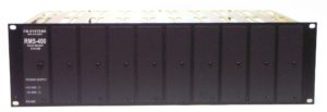
Slide in Rack for 400 Series Cards
The AVI473 AUDIO Video Indicator provides two independent form C relay contact closures for loss of audio and video service. These contact closures can be used to operate an external program switch or remote maintenance alarm. The unit has an audible alarm that can be separately field programmed for audio loss, stereo inversion, and video loss.
A loss of audio program triggers the relay switch after a field programmable time delay. This allows for normal pauses in the audio programming material. The time delay can be set from 1 second to 64 minutes. The relay will switch and the internal alarm will sound when the audio has failed and the count-down time delay has been reached. If the audio is restored before the count-down time delay has been reached, the system will reset the counter and again wait for the audio to fail.
The unit has front panel L.E.D. indicators for Left and Right audio, Stereo Inversion, and Audio Loss.
Audio alarm trigger sensitivity level can be set from the front panel using the “TRIGGER LEVEL” control. You can set the unit to operate on Low level or high level audio signals. The Left and Right Audio indicators are used to set this control.
The video signal loops through the unit so that signal transmission is not lost if power is removed from the AVI473. A field programmable video alarm delay can be set to prevent false alarms caused by short duration sync loss, non vertical interval switching, or any other momentary loss of video.
This unit uses PLL “Phase-Lock-Loop” technology to prevent false alarms due to high level noise. This is especially useful on satellite feeds and microwave transmission, when loss of video produces high level noise. The AVI473 will operate in high level noise environments. A red front panel L.E.D. indicates the loss of video.
Both the audio and video indicators each have an independent front panel switch allows the operator to set the mode of alarm operation. The “AUTO” position will automatically reset the alarm relay when the audio or video returns. The “Hold” position will hold the alarm on after any loss of audio or video, and the “Reset” position will turn off the alarm functions.
The unit fits into the RMS-400 mainframe and power supply. Up to nine AVI473 units can fit into one RMS-400 mainframe.
AUDIOSPECIFICATION
Audio Channels Per Card Stereo Left/Right or Mono
Programmable Time Delay1 Second to 64 Minutes
Input ImpedanceHigh Impedance Bridging
Input Common Mode Reject50 dB minimum, 60 dB average
Input Level (APL)-10 dBm to +8 dBm
Alarm SensitivityAdjustable Trigger Level
Maximum Head Room+21 dBm
Audio Mode Switch Control3 Position Toggle Switch
Audio Loss IndicatorFront Panel Red L.E.D.
Stereo Inversion IndicatorFront Panel Red L.E.D.
Audio Input Status IndicatorsFront Panel Green L.E.D.
Audio Connectors (Balanced)Screw Terminal (Wire)
Audio Alarm Relay OutputForm “C” Relay 1 A @ 30 VDC
Relay ConnectorsScrew Terminal (Wire)
Audible AlarmField Selectable All Functions
VIDEO SPECIFICATION
Video Standard NTSC, PAL, CCTV, (Auto-Select)
Level (Composite Video) 0.7 to 2.0 Vp-p ( 1 Vp-p Std.)Alarm Delay Selector3 Position Low, Medium, HighInput ImpedanceHi-Z, (Loop Through Bridging)Video Mode Switch Control3 Position Toggle Switch
Video Loss IndicatorFront Panel Red L.E.D.
Video Connectors Two, BNC, (Female)
Video Alarm Relay OutputForm “C” Relay 1 A @ 30 VDC
Relay Connectors Screw Terminal (Wire)
Audible Alarm Field Selectable Video Loss
MECHANICAL
Power requirement RMS-400 Mainframe Power Supply
Will Hold Nine Units.
Relays have normally open and normally closed contacts available.
For more information and pricing call: 800-235-6960.


