

WHAT BALANCE BRINGS TO IP VIDEO
The nature of an IP video signal uses a two way communication over two pairs of twisted wire usually packed into a 4 wire pair network cable with an outer jacket to hold everything together. The IP video signal uses a balanced transmission method to deliver its data to the opposite ends of the network cable. By design a balanced transmission system sends equal but opposite signal polarities on each of the two wires in the pair. So when one wire is showing a positive signal the other matching wire is showing a negative signal. In fact the balance on this type of signal transmission is critical to proper operation.
Let’s examine how the signal is generated at one of the transmitting ends. Inside the camera electronic circuitry digitizes the picture information (light) into an electrical signal and by the time it reaches the output connector the signal must match the standards of a network “PHY” or physical layer signal. This layer has standards for its level, balance and common mode interference. Once the digital signal is converted to a serial data stream and ready to transmit it is converted to a balanced transmission by the output driving amplifiers.
It is critical that these output driving amplifiers have a very precise and equal balance on the two sides to prevent any unbalanced signals from being transmitted. Any unbalance in the signal that reaches the receiver at the other end of the system will be cancelled out as a natural function of the receiver. All IP video equipment uses some form of common mode input circuitry that effectively cancels all unbalanced signals so the cancelled signals are lost. If the unbalance is severe enough this loss will adversely affect signal reliability or cause total loss of operation. IP video un-balance is caused by the equipment originating the signals at each end of the network cable and also by the cable itself
. So what can cause the equipment to go out of balance? Well lightning damage is the most common cause of un-balance in an IP system, followed next by ground-loop damage to the IP equipment, and then finally poor quality or damaged cable.
Lightning can damage the output driving impedance inside the IP equipment even if the lightning is not a direct strike, and that has the affect of lowering the output level and if it causes a permanent imbalance in the output signal that too will cause level loss at the receiving equipment. When the lightning strikes a high voltage can get into your equipment through the local ground and generate extremely high current flow in the output circuitry, that usually blows the resistive coatings off of the resistors or damages the semiconductors and it all happens so fast that the coating on the resistors are not even singed.
Ground-loop can have the same affect of damaging the output impedance of the IP equipment over time and upsetting the balance of the signal. With an analog video signal a ground-loop problem can be seen on the video image as a series black horizontal bars on the picture screen, but with an IP digital signal you can no longer see these ground-loop interference signals even though they will damage your equipment by excess 60 Hz AC current running on the wires. This ground-loop current will enter your equipment through the ground of one piece of equipment and travel to the other piece of equipment by the balance wire pairs connecting them. The additional AC ground-loop voltage boosts the current flow in the electronics and slowly cooks the resistors until there resistive values change finally causing IP video failure.
If you install an IP camera and a few months later you have to replace it and then a few months later (about the same amount of time) you have to replace it again you should be looking for ground loop issues. Ground-loop can be the silent killer of your IP equipment.
Cable quality can cause a well balanced IP video signal to go out of balance and create excessive loss in the system. Cable that is poorly made or damaged cable is hard to see physically but can be measured to find out how well it maintains its balance from one end to the other. When a cable is manufactured great care should be taken to see that the insulation has a uniform thickness over the diameter and length of the conductor and that the twists in the wires are also uniform and repeatable. Any non uniformity of the insulation will cause an imbalance in the capacity of the transmission line and create an imbalance that will be cancelled at the receiver. Damage to the cable like stretch cables or too sharp a bend radius or cable that has been flattened by being smashed or particularly wet cables can also cause un-balance even with a good manufactured cable.
It is a good idea to check the balance and levels on every IP video installation you do to be sure your system will stand the test of time and temperature and weather before you leave the job and when you are trying to find the source of an IP video balance problem it is important to know whether to go after the cable or the equipment rather than just replacing things until it works and then hoping that you got it fixed. So what you need is a device to measure these levels and balance the is easy to use and low cost.
The IPM-4 digital video level master is used to measure the signal quality of an IP video network. This low cost meter makes 6 different level measurements to give you assurance that your IP video system is working within specifications. It measures the output levels of both the camera and the recorder end of the system in dBm so you can check the near-end and far-end signal levels and cable loss simultaneously. The meters unique design also measures the percentage of signal imbalance in that exists on both the sending and receiving channels which contributes to cross-talk and increases the bit error rate in your digital video. Then it measures Common Mode signals in dB, a form of interference caused by phase and amplitude variations that also causes video failure.
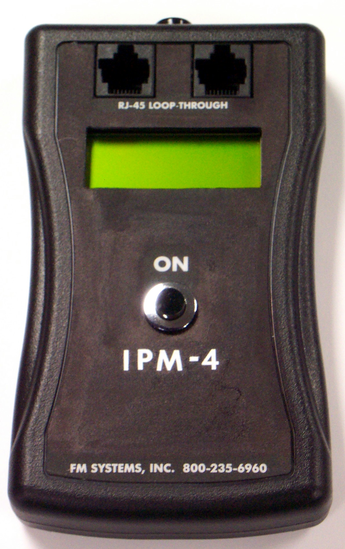
CLICK HERE to get more information about IPM-4

