MEASURING IP CAMERA SIGNALS, WHY DO IT, AND WHAT ADVANTAGE DOES IT PROVIDE?
MEASURING IP CAMERA SIGNALS, WHY DO IT, AND WHAT ADVANTAGE DOES IT PROVIDE?
By: Frank McClatchie
Have you ever had a perfectly good IP Camera System suddenly stop working for no apparent reason, and then taken the Camera to the “Bench” to test it and found out that it works just fine, then done the same with the NVR with the same results, but put it all together, and NO PICTURE AT ALL. Next you replaced the Network Cable, and that did not work either. Next, you replace the Recorder, and it does not fix the problem either. Finally, in desperation, you replace the Camera in the field, even though it did work on the “Bench”, and “lo and behold” the IP System now suddenly works!
Lots of time and money has been spent swapping out equipment to discover what could have been determined by some simple measurements of the system to begin with. There are many variations to this theme, but they all would have been solved much more quickly by simply measuring the signal level Loss of the Network Cable in both directions.
That’s all very good you say, but just how the heck am I supposed to measure the Network Cable Loss with the system up and operating. What instrument can I possibly use to do this that does not cost a fortune or require a shut-down of the equipment? The actual cause of the problem in this case was a lightning strike near the Camera that caused an output resister to change in value, in turn causing a Common Mode Signal, that increased the loss in the IP Transmission.
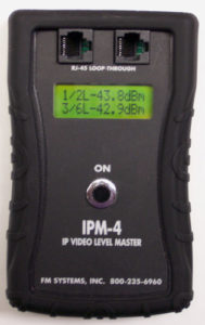
IP Camera signals have been rather difficult to measure in the “field” because what instruments actually exist to do this kind of measuring have been too large, too heavy, and too expensive for installers to utilize. This has all changed with the introduction of the new IPM-4 Signal Power Meter that will help you measure the IP Transmission Signals in both directions while at the same time being small enough to fit into a shirt pocket. It is also a great deal less expensive than a Laboratory Instrument. Most power measuring meters, capable of measuring the entire IP Frequency Spectrum, cannot even be directly connected to a Network Cable because their input impedance is too low. The IPM-4 meter is designed to directly connect to any Network Cable and measures the IP signals in both directions. It also measures the balance of both the near end and far end transmission and any Common Mode signals that may be present on the Network cable.
It is now possible to purchase an inexpensive IP Power Meter that reads the power level of an entire IP Camera Signal over a range of greater than 30 dB, to an accuracy of 0.1 dB. Since the maximum usable loss encountered by an IP Signal is about 18 dB, this is more than sufficient range to meet any situation. The Common Mode Interference must be measured with normal IP signals actively transmitting. All the measurements are made on the live IP video path.
The Camera, Network Cable, and the NVR are all capable of creating a Common Mode Signal. The Camera and the Recorder can generate a Common Mode signal simply by having an incorrect source impedance on one or both sides of the “balanced” source drive. Assuming that the source impedances were exactly correct (that is, 50 Ohms resistance on each side of the pair of transmitting impedances equal to 100 Ohms), any excess current flowing through those transmitting impedances can cause the driving impedance to change permanently and thus generate a Common Mode Signal that may cancel picture transmission or add to the loss in the transmission path. Any large 60 cycle Ground Loop Current that gets onto the Network Cable can slowly damage the output drive resistors and create a permanent resistance change that will generate a Common Mode signal thereafter that may be sufficient to stop transmission of the IP Signal. A nearby lightning strike can do exactly the same thing but the damage to the resistors is instantaneous.
The generation of a Common Mode signal within the Network Cable itself can be caused by a number of different physical conditions that can take place in the Network Cable due to displaced cable pairs or any squashing, stretching, or contorting of the cable as well as water in the cable.
The Network signal in one direction actually has two separate signals for one path, because there are two different drive amplifiers, one driving each wire transmitting the digital signal and velocity of signal transmission on the two wires must be exactly identical, if they are to arrive at the opposite ends of the wire at the same time. If there is anything that changes the differential speed, the two successive pulses may interfere with each other and cause a sort of internal cross-talk which is referred to as a Common Mode Interference. Thus, both equipment terminals (the Camera and the NVR), and also the Network Cable itself, can generate an interfering signal, and block transmission of an IP Picture Signal.
When you are having trouble identifying exactly which of these three parts of the IP Transmission System is blocking the IP Transmission, how can you know just which part must be serviced? The matter becomes quite simple, if you have an IPM-4 Signal Power Meter to measure the signal levels of the IP Transmission System, as well as the balance at both near end and far end, and the Common Mode interference that is being created within that system.
One of the basic problems is that the Manufacturers of NETWORK CABLE generally do not publish the actual Transmission Loss of their Network Cables. Instead of the actual Loss of the Cable being stipulated in the sales literature, a term called the “CATEGORY of a Network Cable is used.
The Category terminology would be more useful if all Cameras, NVR and Network Switches were manufactured with exactly the same input receiver signal sensitivity, but they are not, so some “Category 6” cable will “reach” further than others.
A step in the right direction would be for the manufacturers of Network Cable to start publishing the Loss of their specific Network Cable in dB per unit length. Then the manufacturers of NVRs, and switches could also publish the sensitivity of their devices in dB so that installers could estimate whether a given combination of Cameras, Network Cables lengths, and NVRs would actually work when connected together.
Category 6 cables tend to have an actual Signal Loss at 100MHz of about 20 dB per hundred meters, but there is considerable variation to be found in cables manufactured in different locations and manufacturers. If you own an IPM-4 Signal Power Meter, you can test any manufacturers cable to see what the signal loss of a specific Network Cable actually is. That loss will give an accurate indication of the quality and how far a picture can be transmitted on any given cable.
Network Cables vary more in Signal Loss than Coaxial Cable mostly because of the construction technique used to manufacture the cable. The actual loss of a network cable can vary widely do to the consistency of the “twist” in the wire pairs, as well as many other factors, too numerous to go into in this discussion. but one of the main sources of Cross-talk and variation of loss between cables is the fact that the wire pairs are not individually shielded, except in the case of Category 7 cable. The Category 5 and 6 typically have no shielding of any sort within the cable. and, that type of cable depends on the presence of the other pairs in the Network Cable to provide some slight shielding effect. Since the spacing between the wires constantly changes the effective capacity also changes, thus varying the impedance of the wire pair and cable loss throughout the length of the cable according to how much the cable is compressed and stretched along the length. This is also one of the main reasons that Common Mode Signals can be created along the length of the cable.
Once a differential data signal is converted into a Common Mode signal by the non-uniformity of the wire pairs, it is immediately subject to radiation away from the cable, just as if that cable were actually an antenna leaking the signal, and that part of the signal cannot reach the other end of the cable, thereby increasing the “Cable Loss” that can result in the complete loss of picture transmission.
To answer the Titled Question, the reason why the frequency response of the IP signal channel should be measured is quite simply, to discover why one IP signal can be transmitted over a specific transmission facility and another cannot be transmitted over another seemingly quite similar facility. Of course, the advantage of doing so is that once you understand the limitations of a Transmission System you are much more likely to be successful when installing other systems. Besides, it is fun to know what’s going on inside the network cable, and it will give you more flexibility with your installations.
It is the dB relationship between the signal power from the far end verses the signal power at the near end that is the measure of Cross-talk and that also determines whether any given IP System will operate correctly.
It is also the Common Mode Signal that is created within the Camera, NVR, and Network Cable that “robs” the desired Differential Data Signal of some of it’s original Signal Power. The Cross-talk can also interfere with the desired Differential Data Signal.
HOW TO COMPUTE IP PICTURE TRANSMISSION POWER LEVELS.
The process is very direct. Simply measure the power output of the Camera in dBm, subtract the power loss of the Network Cable, and compare that result with the necessary input power level needed by the NVR. To discover the dBm level sensitivity of the NVR you can attenuate the input signal up to the point just before a failure occurs. That will put the system at the digital margin, the edge of operation and that is equal to the minimum power level required by the NVR, then measure that level. You can use the IPMT-3 Video Margin Tester to find the minimum signal level required to operate any IP Camera, NVR, or network Switch.
But just to be on the safe side, it is always a good idea to measure both the power output, and BALANCE of the camera and NVR to ward off possible surprises, in case a camera has a low power output, or possibly is generating an excess Common Mode signal, due to an unbalanced output drive. These conditions can be easily be measured with the IPM-4 Power Meter.
Next, it is a good idea to measure the actual signal Loss of the Network Cable after the Network Cable is installed to see if the installation process has damaged the Cable Loss curve in any way.
Measure the Camera Output after the cable run at the NVR input, to determine whether there is sufficient power present to receive a solid Picture signal.
Camera and Recorder measurement have shown that there is considerable variation between various manufacturers of Cameras and Recorders as to the actual Signal Power Level that these devices will operate with. If the Camera and the Recorder operate on widely different power levels, then there is also the possibility of Near-end or Far-end Cross-talk taking place that would also block IP picture transmission, even if the cable falls within the nominal cable lengths permitted by the IP Transmission System.
Measuring IP Camera power output, the Network Cable Loss, and knowing the NVR receiver sensitivity can insure that any given IP System will operate correctly when it is turned on. No Surprises when the system fails to operate correctly, as long as there are no actual equipment defects, and even those can be found out by dB power measurement of the IP System.
dB OUTPUT POWER OF THE IP CAMERAS AND IP RECORDERS.
The Power Output of IP Cameras and Recorders can vary a great deal, and since it is necessary to know just exactly how much power an IP Camera and Recorder is putting out in order to know whether the signal will be strong enough when it gets to the far end of the Picture Transmission System, it is necessary to measure these power levels.
The Camera is supposed to have a power output of zero dBm, however the power output may be much higher. Some of the Cameras will measure as much as +10 dBm depending on which Company manufactured the Camera. In order to reduce Near-end and Far-end Cross-talk, it is a good idea for the Recorder and the Camera to have similar output powers. This can be easily measured by the IPM-4 Signal Power Meter at each end of the system.
Once you have the Output Power (in dBm), the Transmission Loss (in -dBm), and the receiver Sensitivity (in -dBm), you can add them all up to see if you have enough signal strength to reach the far end terminal with sufficient excess power to overcome any extra power losses that might be encountered.
This dBm signal measurement system is not a new thing. The same exact process is utilized on every Long Haul telephone system in existence today. At first the measurement process may seem overly complex, but upon repetition, these measurements are actually quite simple, and insure correct operation every time.


