VIDEO LOSS AND RELAY CONTROL ON AN IP NETWORK
VIDEO LOSS AND RELAY CONTROL ON AN IP NETWORK
By: Don McClatchie
Ethernet networks are popping up all over the place connecting security cameras to recorders, Peer to Peer communications, remote control and telemetering in ways never imagined. Since many IP signals are routed by switches and bridges it is possible to use this communications system to run other control signals to do a host of interesting things. All that is needed is to configure your control signal into that which can be connected to the Ethernet and sent on its way to the destination equipment for control. If you have a device that will allow transmission of switch contacts over an IP network then you can add control signals onto the network and use them to control other equipment, turn things on and off or send an alarm or when you need to know the condition of other equipment.
For instance, in some states and in Canada the regulations for gas station pumps require a video camera to be placed to observe the fuel transfer. Equipment must be placed inline with the camera to detect failure of the camera and automatically shut down the pump when a camera fails, so no fuel can be pumped without observation. In Canada this regulation is referred to as the TSSA ruling and it states that “Every filling position must be covered by a camera”, “Cameras must meet the license plate clarity test”, “Cameras must have a video loss shutdown function”, “A camera can cover more than one filling position provided it meets the license plate clarity test”, “Filling positions may be located within 360 degrees and 50m of the attendant console and within the facility lease property line”. The term “Clarity Test” means that the attendant shall be able to identify the jerry can or read the equivalent front of a license plate.
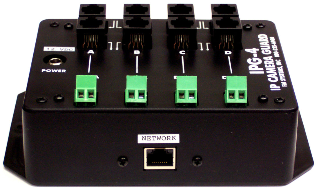
So, for the IP cameras you must purchase a device that can detect the loss of the IP camera signal and transfer that information to the pump shut off control system. The pumps must be shut down and disabled when a video camera stops sending its signal. One such piece of equipment is called the IPG-4 IP Camera Guard video loss relay. Just loop the video through the unit and connect the pump controls to the relay output connector. However, to wire the pumps that way does require a wired connection from the pump islands to the pump shut off control equipment or a direct star configuration where each camera cable returns directly from the pump island to the building where the pump shut off control is.
If you find that you have no direct wires to run to the control system or you are using a data switch to combine camera signals, then you can use a different piece of equipment to detect the camera signal loss and send the relay control over the same IP “Ethernet” connection that carries the combined IP video cameras.
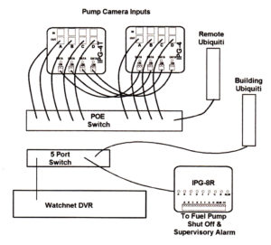
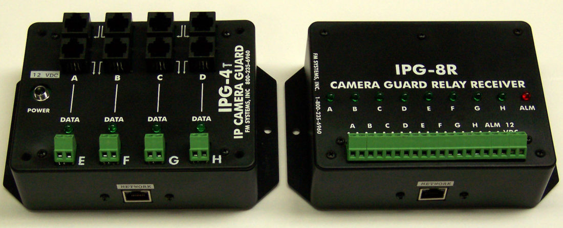
This equipment is called the IPG-4T unit. It monitors up to 4 IP cameras and sends a signal over the same ethernet path that the camera signal uses to return the video loss signals back to the pump control system. The IPG-4T also has 4 additional relay contact inputs to add on a second group of 4 IPG-4 camera detectors for a total of 8 camera video loss signals on one IP “Ethernet” path.
Basically, the IPG-4T has an 8P8C “RJ45” connector to connect all 8 of the detector outputs to the Ethernet switch or network combiner. The IP camera signals are monitored at the gas pumps, then the information is encoded and sent back to the pump control system by an Ethernet signal. At the other end of the network run the signals are converted from an IP signal back into the original relay control signals by a device called IPG-8R and output as relay contacts for direct use at the pump control equipment.
One IPG-4T and one IPG-8R can monitor and transmit the video loss information on 4 video cameras and with an additional standard IPG-4 unit, you can have 8 cameras monitored for video loss and delivered over the network. The IPG-4T and IPG-8R are used when it is not possible or prohibitively expensive to run control wires from the pump islands to the control panel or when the cameras use a network switch to combine signals for transmission on a single cable or wireless unit. This equipment makes it easy to install IP camera video loss detectors anywhere and deliver the control signals over an IP network.
Both the IPG-4T and IPG-8R have configurable addresses so they can be programmed with any laptop or computer to work in any network. The units come already programmed and ready to use. You can re-address the units to match your network requirements. An easy to use web-based utility can be downloaded to address the units to match your network application. For more information or to order this product call 1-800-235-6960 or go to fmsystems-inc.com.
A typical 8 channel customer application over wireless IP


