IP VIDEO MARGIN, WHAT IS IT AND WHY SHOULD YOU CARE?
By: Don McClatchie
IP video is a relatively new technology and with it comes new installation techniques and tricks of the trade for the installer to learn. The advantages of using IP video cameras and recorders are obvious. Higher definition cameras are available, the cable slope loss will not degrade the video image, and when you connect the network cables you get a picture that is as sharp and clear as the camera can produce. That is of course, if your video margin allows you get a picture at all.
IP video does have its limitations and when you reach those limits you will get a total failure of the system to deliver any kind of a picture. Unlike the old analog cameras that would give you a dull washed out picture when the signal level was too low, IP cameras will give you a perfect picture until the cable loss reaches beyond the minimum allowable signal and then you suddenly get no picture at all. This effect is called the digital cliff, because like walking off of a cliff, everything is great till you take the last step off the edge and then all is lost.
IP VIDEO MARGIN is the amount of signal level above the digital cliff that you have in your system to prevent a failure from occurring. The question is how much margin is there in your IP video system, how close are you to falling off the cliff, and how can you measure it?
First let’s look at what causes this loss of the network signal. Signal level loss and high frequency roll-off in the network cable also called “cable slope loss” are the main causes of most failure. Reactive loss is the predominant loss of signal level and is caused by the distributed inductance of the wires and the distributed capacitance between the wires with a small additional loss due to the loop resistance of the wire. So what effects cable loss the most is the insulating material, twists of the wire and the uniformity of manufacture of the cable, not so much the gage of the wire although increasing that does help some.
The rate of wire twist and uniformity of twist strongly affects inter-pair cross-talk between active pairs in the cable and ultimately this sets the maximum distance that a cable can be used. In the manufacture of cable the magnetic and electrostatic forces within the network cable must be precisely controlled to prevent Common Mode cable loss. When all the equipment is working correctly common mode loss is caused by slight mechanical defects in the manufacturing of the cable.
Small changes or irregularities in the twist of the wires or non-uniform insulation thickness on the wires can cause a long cable to have unusually high common mode loss. Network cable loss is also affected by the temperature and humidity, not to mention water infiltration into the cables outer jacket and wire insulation. This common mode loss will directly affect the maximum distance you can go with a network cable and it can change with time.
Temperature effects are a daily change in the loss of the network cable. However humidity and water intrusion is a lasting slowly progressive loss that will take the system down over time. In particular the consistency of the rate of twist and the diameter of the insulation must be very closely controlled over the entire length of the cable. Some manufactures control these parameters better than others, so if you find a good manufactured cable stick to using that brand for repeatable results.
The manor in which the cable is handled and installed will also have a great effect on cable loss and over all system integrity. When installing network cable try not to stretch the cable when pulling it into conduit, this permanently changes the wire diameter and insulation thickness damaging the cable and creating greater loss in the cable. Also twisting, kinking, or bending the cable in a radius sharper than 5 times its diameter will create additional loss in the cable.
So now that you have installed your IP system, how do you test for the margin? What you need to know is how much additional loss can the system take before it fails and how close are you to having a failure? You will want to know if you are on the edge of the digital cliff before you finish the job so you can walk away with confidence that the system will continue to operate when cable losses change slightly.
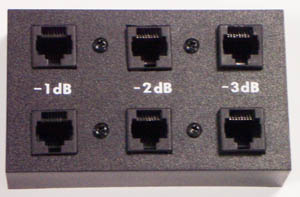
The easiest way to test for this margin is to use the IPMT-3 IP VIDEO MARGIN TESTER to insert a know amount of loss in steps into the signal path and see how much additional loss the system can stand and still deliver a picture. This loss is measured on a dB scale and you should have at least 3 dB margin for a safe operating system. A loss of 3dB is the equivalent of a 29% drop in the operating level of the system. By using the other loss steps on the unit you can determine if you have enough margin to reliably operate the system under all conditions.
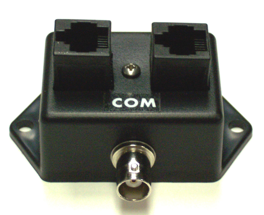
The IPMT-3 is a low cost inline attenuator for testing IP video margin equipped with 8P8C connectors to fit your network cables directly. Simply loop your IP video signal through the unit starting with the highest attenuation and when the system displays a picture you will know the amount of margin your system has and then you will know with confidence how much additional loss the system can withstand. Most importantly you will know your system is not sitting at the edge of the digital cliff waiting to fall off.
Measuring this margin is a must for all installations to give you the security of knowing your system is capable of withstanding additional loss and still operate properly. You can also use the unit to perform periotic testing to insure that you maintain your margin of operating safety.


