HOW TO TEST A FAILED VIDEO CAMERA
HOW TO TEST A FAILED VIDEO CAMERA
By Don McClatchie
Have you ever gone out to replace a bad camera, only to find that it starts working again when you wiggle the wires or reconnect the video or power cables? When that happens, the installer might just continue to change out the camera in the hopes that doing so will solve the problem. Next the installer is called back to the jobsite with the same camera failed again. This problem is embarrassing, expensive, and a lot more common than you might think. But with the right procedure and a little testing, it can be avoided. This process is a step by step series of tests to find the source of the camera problem while the camera is in fail mode.
Step 1, and most obvious step is to identify which camera has failed by observing all the video camera images at the DVR. At this point do not disconnect or wiggle any wires.
Step 2, go to the failed camera and use a (VOM) Volt Ohm Meter set to Low DC scale to measure the “Loaded Voltage”. This is the Voltage at the cameras power supply input terminals, if the camera uses an attached “Dongle” type of power connector with twin lead wires you can poke a pin through the insulation on each one of the twin lead wires and use them as test points to measure the Voltage. The pin hole will close up after removal of the pin to seal the wire and that is better than stripping the special connector wires at the camera. Or you can make up a power wire break out tool that uses the same power connectors normally found on your cameras like the one featured below. The alligator clips are you’re your voltmeter.
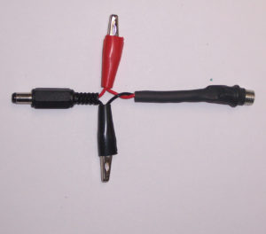
POWER ADAPTOR
Make sure that the voltage is in the range of operation for the camera you are testing. It is important to measure the camera supply at the camera while the camera is powered up to get a proper reading of the operating voltage including the “I/R” voltage drop caused by the power wire run. BE SURE to record the voltage readings for later comparison.
In some cases, the camera has failed due to “Camera Starvation” caused by under voltage. For example: The camera works during the day and has a marginal working voltage at the camera, when the lights go out and the camera turns on a set of IR L.E.D.s and the extra current draw used for those illuminators lowers the voltage below operating levels for the camera and it goes down (no picture), at the same time the electronics that control the L.E.D.s also fail and cause the IR illuminators to stay on all the time regardless of the lighting levels. This is a kind of lock out that is caused by camera starvation.
In other cases, you might find that the Voltage level is too high, and that can result in two issues. The first one is camera power overload by powering the camera with a supply voltage outside of the specifications. Inside most cameras are components called PTC automatic resettable fuses, they are over current protection devices that open up (go to high resistance) when they get hot, but unlike a fuse that burns out, they just cool off and reset when the power is disconnected from the camera, turning the camera back on.
When a camera is operating at voltages above the specifications they can pop the PTC when the camera gets warmer than usual like on a hot day. Once the PTC fuse pops it will only reset after the power is removed and then re-applied, so it is important to measure the power supply at the camera “loaded” before turning off the power.
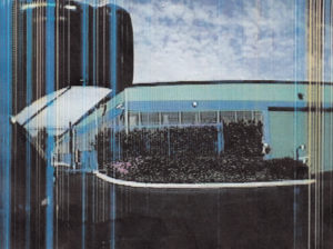
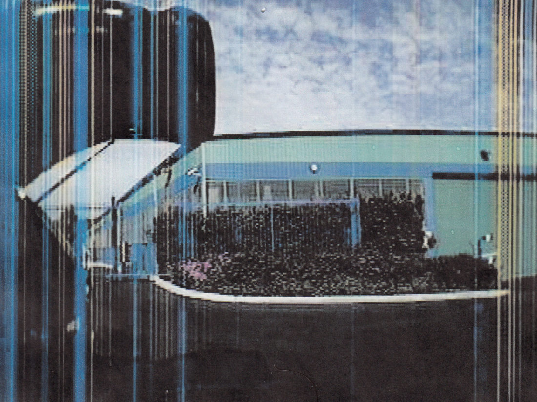
There is one more thing to mention about operating cameras above the specified power requirements. The image below is a fail condition caused by over voltage on a DC camera, in this case the camera was overheating due to over voltage that caused failure of the CCD (Charged Coupled Device) the component that captures the picture and turns it into electrical impulses. The vertical color lines were caused indirectly by the overvoltage on the camera. Of course, this camera was sending a picture but is was not obvious that overvoltage was causing the problem.
Step 3, is the check for Ground Loops, remember up until this point we have not disconnected any wires or cables. To make this measurement you need the same VOM set on low AC voltage scale. Now you must disconnect the video coaxial cable at either end of the cable run, since you are at the camera end disconnect the cable from the back of the camera. Use your VOM meter with one probe on the coaxial cable shield (the outside metal part of the BNC connector) and with the other probe touch the BNC connector outside shield part on the camera.
Basically, you are measuring the AC voltage that exists between the cameras ground and the DVRs ground using the cable run back to the DVR. If you measure a level a AC voltage larger than 1 Volt, then you may have a camera locked out of the DVR due to video overload. This is a condition that exists when the video level exceeds 160 I.R.E. units or about 1.142 Volts of video. DVR (Digital Video Recorders) are digital devices that have been programmed to accept normal video levels of 1 Volt in level and the designers built in a headroom or excess operation level of about 20% for over level signals.
Unfortunately, many DVR designers used 1 volt as the standard for video level when in fact a fully saturated color video signal is 1.142 Volts peak to peak, so the DVR is very sensitive to over level and does not have much margin for over level signals. Ground loop voltage adds directly to the video voltage and can disrupt DVRs causing them to show no video signal at all.
If you have a ground loop voltage small than 0.1 Volts AC then you have a ground loop, however that level would not lock up the DVR and prevent a picture from being seen. However, ground loops change with the power use in a building and that small ground loop can spike up when heavy current equipment in the building is turned on, so it is possible that a seldom occurring spike can trigger camera loss in the DVR. If this is the case, then the camera and DVR will show the picture after you reconnect the failed cameras video cable.
Step 4, if you have a test equipment to check the video level like an oscilloscope or CM-2 Camera Master you should check the video levels coming from the camera. This can be done at either end of the cable by looping through the test equipment and measuring the Sync signal first, it should be about 40 I.R.E. units if the video end of line terminations are in place. If the Sync reads closer to 80 I.R.E. units then your end of line termination is not in place and could be causing DVR overload. Next check the Luminance or White level of your video signal. It should be 100 I.R.E. units and not over 120 I.R.E. units. Again, anything near or over 120 I.R.E. units can cause DVR overload. Measuring the different parts of a video signal can save you time when trying to find a problem on a camera. This meter will make these tests on HD-TVI and HD-CVI camera as well.
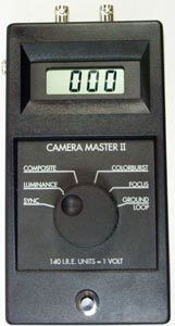
CM-2 Video Master Test Meter
Step 5, if your failed camera has not come back on then cycle the power supply off and then back on again. Did the camera come back on? If so, then repeat the step 2 and compare the voltage readings to those taken from before. If there is a change of many volts in the readings, then it is possible that your camera is suffering from overload or starvation (check the camera specifications) and you should look at using a larger (more current) power supply or move the power supply closer to the camera. If the camera is on and it is in full daylight or a well lit room, simulate darkness by covering up the day night sensor with your finger or cover the L.E.D. illuminators with your hand to turn on the illuminators for full camera power supply load. See if you can induce the camera to fail again.
Step 6, is to check the coaxial cable for an open or a short circuit, this is done with your VOM set on Ohms. Use a BNC barrel and a 75 Ohm termination at one end of the cable with the DVR and camera disconnected. Use your Ohm meter at the other end one probe on the shield and the other probe on the center conductor. You should measure a minimum of 75 Ohms and a maximum of no more than 150 Ohms depending on the length of the coaxial cable. The reason for the 75 Ohm termination at the opposite end of the cable is to make sure that there are no short circuits along the cable length. If you read less than 75 Ohms then you have a short circuit or a wet cable or some other simi-short that reduces the cable shunt below 75 Ohms.
Step 7, to measure the power supply wires for continuity. Problems can be created by faulty power wiring. If you have a DC powered camera that is on and working and you disconnect the negative power wire and it continues the work, that is an indication of bad wiring and a break in the negative power wire. I have seen this, and it creates odd image problems associated with ground loops in the main power system. It is possible to measure the loop resistance of the power wires by disconnecting them at each end and shorting one end, then use your Ohm meter to check it out. However, it would be better to put a resistance at one end like you do for video cable just to make sure that you don’t have a short circuit somewhere along the line. Understanding why a camera failed we give you the confidence to solve the problem quickly and correctly.


