

SUBCARIERS IN MICROWAVE AND SATELITE SYSTEMS
SUBCARRIERS IN MICROWAVE AND SATELLITE SYSTEMS
By: Frank McClatchie
FM SYSTEMS, INC
1-800-235-6960
SUBCARRIERS DEFINED:
In the early days they were called Diplexers, alluding to their main function at that time, to place a second channel (TV audio) onto the same base-band signal as the television video signal for TV studio-to-transmitter (STL) microwave links. After a while, two or more channels were multiplexed onto the STL systems, so the term Sub-carriers came into prominence. The term Sub-carrier is now applied to a host of multiplexing processes that are carried in the frequency band above video, typically ranging from 4.5 – 10 MHz. In fact some channels have discarded the video and carry only audio sub-carriers.
ARE SATELLITE AND MICROWAVE SUB-CARRIERS THE SAME?
A given type of sub-carriers may in fact be operated over both, but these two transmission facilities differ in some important characteristics so that a sub-carrier designed for one may not operate as well on the other.
The Microwave facility is characterized as having an excellent carrier-to-noise ratio (C/N) under normal conditions, only dropping to threshold a very small percentage of the time, while a satellite channel operates just above threshold all the time. This causes the choice of design factors relating to signal-to-noise ratio to be more crucial in satellite systems. Conversely, since the satellite is a one-repeater system, while microwave systems may extend up to 50 or more links for one channel, in microwave sub-carriers the design factors that reduce the impact of differential phase, differential gain and envelope delay are predominate in importance. Sub-carriers are not all created equal.
WIDE-BAND SUBCARRIERS:
In general these sub-carriers deviate from +/- 75 KHz to +/- 500 KHz and carry un-companded program audio, F M stereo multiplex, BTSC multiplex, 12 channels of frequency multiplexed voice grade or wide band data (up to 100 KB or even more). This type of sub-carrier accounts for most of the satellite TV audio channels and most of the microwave sub-carriers.
The high deviation ratio enables these channels to provide good S/N ratio, even on satellite facilities. The wide band occupancy restricts the number of sub-carrier channels that may be carried. Up to four such sub-carriers have been carried on terrestrial microwave and usually no more than two are carried on satellite transponders.
The 15 KHz program audio type of wide deviation sub-carrier is what started the sub-carrier business. They are still widely used, but are falling out of favor as operators discover that 15 KHz program audio can be transmitted on companded narrow-band channels that allow double or triple the number of channels to be transmitted over the same microwave or satellite facility.
Wide-band sub-carriers retain their usefulness when transmitting base-band multiplexed signals such as FM stereo multiplex, BTSC multiplex, wide-band data, and multi-channel frequency division multiplex (FDM) voice grade channels (see block diagrams of these types of systems in figures 2, 3, 4, 5, and 6).
NARROW-BAND SUBCARRIERS:
Narrow-band sub-carriers usually deviate +/- 25 KHz to +/- 50 KHz and carry companded program audio or Frequency Shift Keying (FSK) data up to 9.6 KB. Companding of some sort is necessary because the narrow deviation results in a low deviation ratio and thus poor basic S/N ratio. The +/- 25 KHz deviation sub-carrier is usually limited to transmitting 7.5 KHz audio, while +/- 50 KHz deviation transmits 15 KHz program audio.
The most common narrow-band satellite facilities use a sliding pre/de-emphasis system developed by Wegner. At high volumes, the channel frequency response is flat. As the program audio level is reduced, a de-emphasis network time constant is progressively increased at the receiving end. Since the transmitting modulator is pre-emphasizing with the same dynamically controlled time constant, the overall frequency response should remain constant. The result is that at low modulation levels, the high frequency response of the receiver is greatly reduced, thus reducing the level of received noise accordingly. The main shortcoming of this system is that when the pre-emphasis at the transmitting end gets out of step with the receiving de-emphasis network, the frequency response is no longer flat. Any difference in level at the receiver versus the transmitter will cause changes in the frequency response.
This system is in widespread use on non-TV audio (radio programs and other audio services) on satellite facilities. The sliding de-emphasis systems are available from Wegner, and FM SYSTEMS, INC. and perhaps other manufacturers as well.
Various other types of compandors are in use in satellite and terrestrial microwave facilities in order to overcome the fundamentally poor S/N ratio of narrow-band sub-carriers. Most of these systems are proprietary and are usually available from only one company. These systems consist of one-band or two-band compandors with either 2:1 or 3:1 compression ratios. The cross-over frequency of the more common two-band systems will vary according to manufacturer, as will the companding ratio and attack/release time ratios. With such variation in operating parameters, the receiving sub-carrier should match the transmitting system to get the best performance. However, “mixing” types of modulators and de-modulators sometimes works surprisingly well, most listeners cannot distinguish any significant difference between basically similar systems. The most common companded systems are:
1. PANDA II, by Wegner.
2. STUDIOLINE, (2 band, 3:1) by FM SYSTEMS, INC.
3. BROADCAST COMPANDOR (2 band, 2:1) by FM SYSTEMS, INC.
Narrow-band channels are also used to transmit FSK data. Up to 19.2 KB data rates can be transmitted on +/- 50 KHz deviation type of narrow-band system and up to 9.6 KB can be transmitted on the +/- 25 KHz deviation sub-carrier systems.
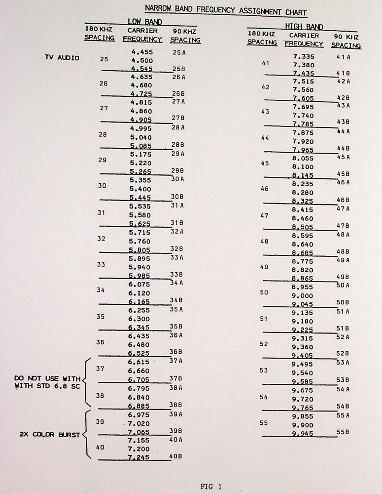
Each of the two band-widths of narrow-band deviation sub-carrier systems are assigned to specific frequencies (see figure #1). Note that the first sub-carrier frequency is 4.5 MHz, and is assigned channel number 25 This is because 4.5 MHz is the 25th harmonic of the 180 KHz frequency spacing interval. All other frequency assignments will be whole number multiples of the 180 KHz frequency spacing.
These channels will be deviated +/- 50 KHz and be capable of passing a 15 KHz base-band audio signal. Since most 4.5 MHz sub-carriers are for TV audio, deviation on this particular channel is +/- 25 KHz, and contains no companding.
The lowest frequency commonly used is 5.4 MHz. If this frequency is not used, the two +/- 25 KHz channels (5.355 and 5.445) may be used. In each case, either the 180 KHz spacing channel may be assigned or the two 90 KHz spacing channels may be operated, but never any combination of the two within one frequency interval.
DELTA MODULATION SYSTEMS:
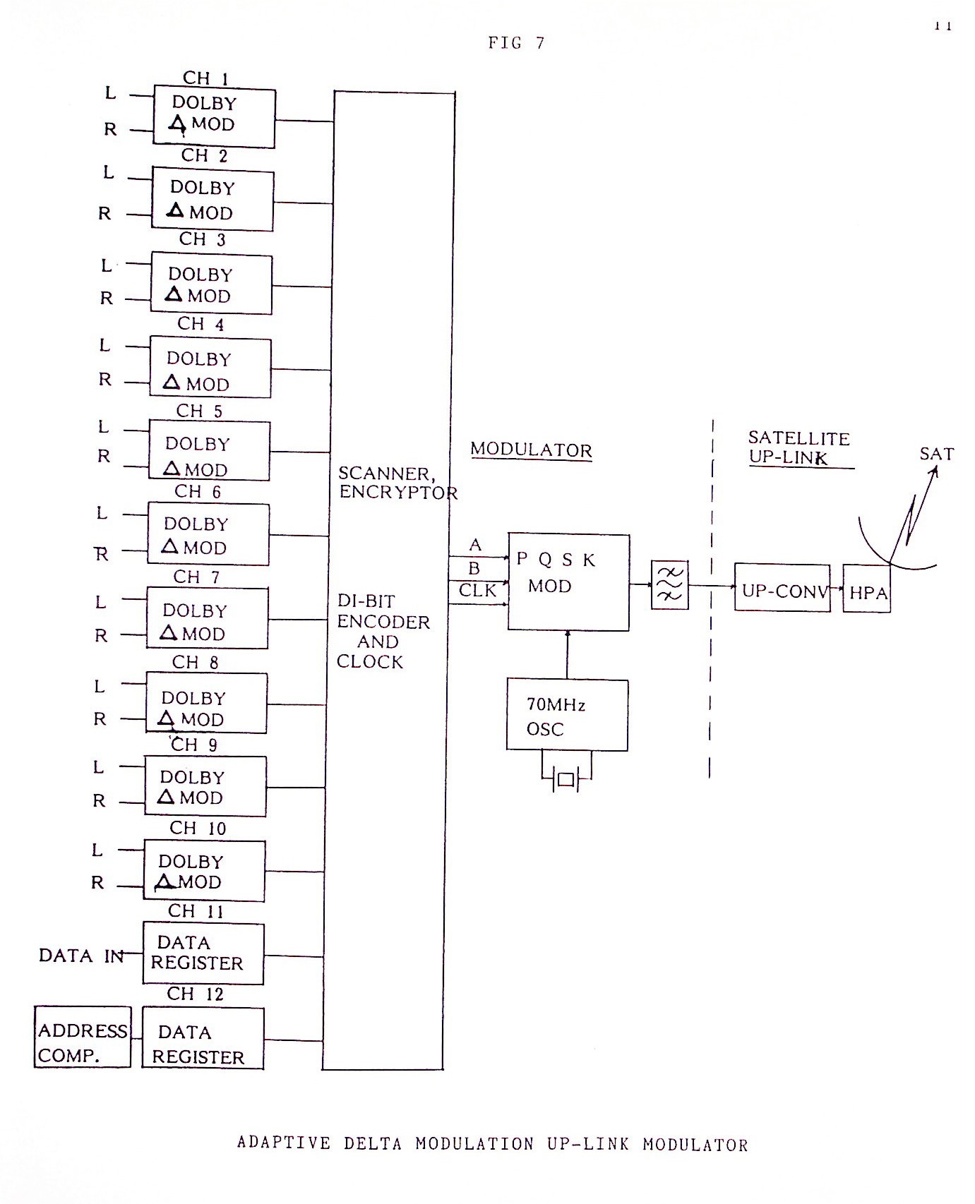
These systems usually use one of the versions of delta modulation developed by Dolby Labs. In this system the audio signals are sampled at a very high rate, then the difference between the current sample and the previous sample is determined by subtraction. This difference is encoded into a bit stream along with step size encoding and sliding de-emphasis. This is referred to as Adaptive Delta Modulation. This bit stream is usually modulated onto a carrier by the Quadrature Phase Shift Keying (QPSK) modulation system. At the present time this process is in use on a satellite transponder to transmit VH-1. The decoders for VH-1 are available from Wegner. Various countries are currently experimenting with the Dolby Adaptive Delta Modulation system.
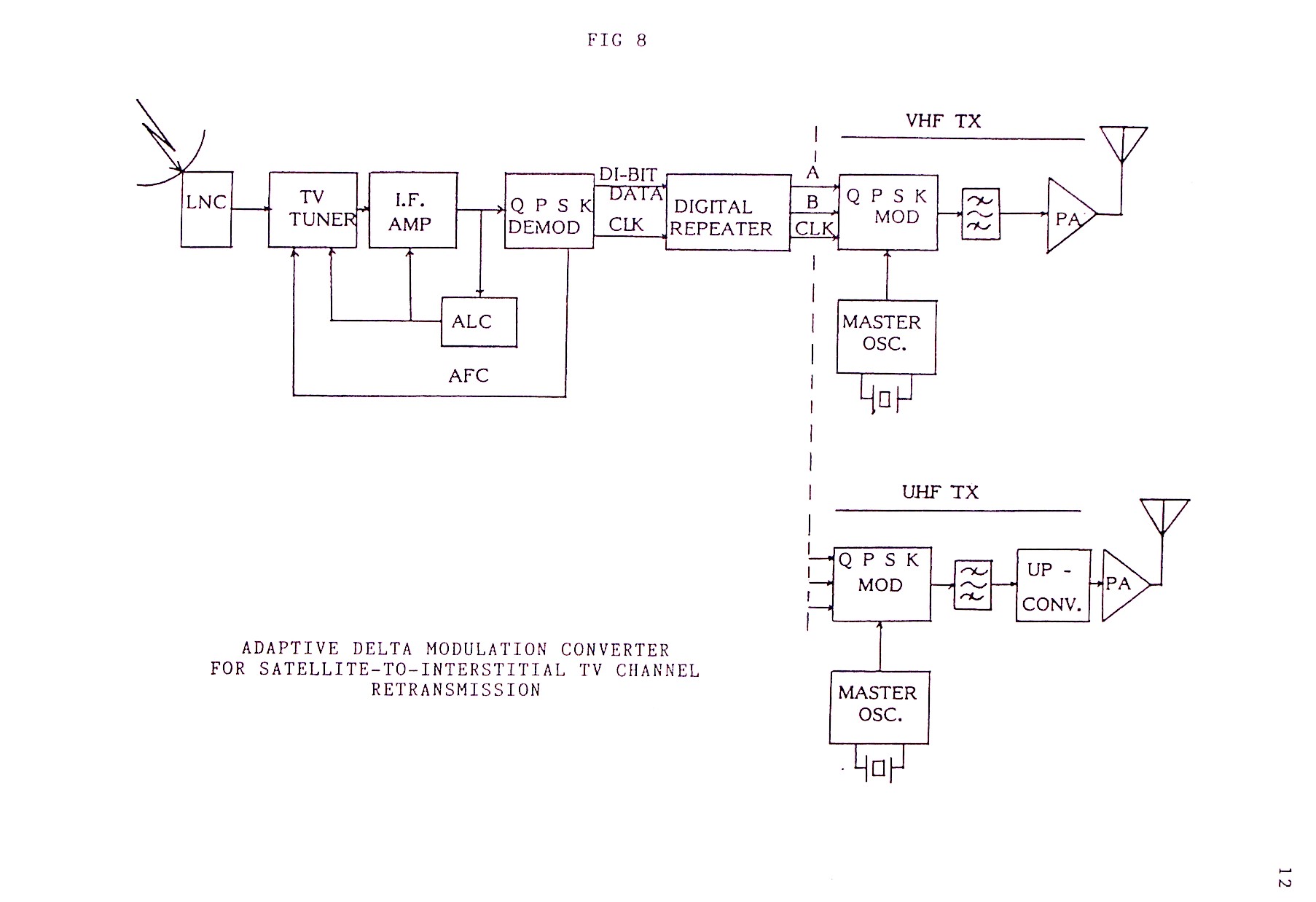
In the U.S.A., a 12 channel system is being designed by FM SYSTEMS, INC. for the Digital Radio Corporation. This system can carry any combination of data and stereo or monaural program audio signals. Each data channel can carry 512 KB and each program channel can carry either two 15 KHz audio channels or one 15 KHz stereo channel. The band width of this system is 6 MHz (to the -60 dB points), so that transmission is possible on any facility intended for video, such as Direct Broadcast Satellite (DBS), Multipoint Distribution Systems (MDS), and Interstitial Television Channels (ITC). The Dolby Adaptive Delta Modulation system occupies a fraction of the band-width required for digital modulation processes, so 3-5 times as many channels can be transmitted in the same band-width (see figure 7, 8, and 9).
Note that the Adaptive Delta Modulation system requires very little more spectrum than FM stereo multiplex. FM stereo multiplex requires 4.8 MHz to transmit twelve channels, with energy right to the band edges, while the 12 channel Delta Modulation system requires 6 MHz, but is 60 dB down at the band edge. Another advantage is that Delta Modulation can operate at a 13 dB Carrier-to-Noise ratio (C/N) while FM stereo requires a much higher C/N. Also the Delta Modulation system can deliver 80 dB S/N, while FM multiplex rarely exceeds 65 dB. Widespread use of Delta Modulation is still in the future, but this system has much to recommend it and will be worth watching.
SCPC THE FIRST COUSINS OF SUBCARRIERS:
A discussion of sub-carriers would be incomplete without mention of Single Channel Per Carrier (SCPC) systems. These channels differ from sub-carriers in one crucial respect, but otherwise sub-carriers and SCPC have much in common.
The sub-carrier is characterized by first adding the sub-carrier to the TV signals at base-band, and then Frequency Modulating this composite onto one carrier, while SCPC Frequency modulates video, audio and other signals onto separate carriers, then adds them together to form the composite signal. This difference in sequence between addition and modulation results in some very interesting consequences.
Sub-carriers and any video signal must be combined at one physical location as a composite base-band signal, at that point all signals are modulated on the one carrier. So sub-carriers must be up-linked to the satellite from a single location.
SCPC carriers are added together after modulation, so each SCPC carrier may originate from different geographic locations. This geographic freedom enables much more flexible communications systems to be built. SCPC systems are multiple origination systems while sub-carriers are single geographic source systems.
The main design differences between the sub-carriers and SCPC channels are that SCPC channels usually operate in the I.F. band between 52-88 MHz and the modulators may require a frequency dispersion signal, and the receiver usually must contain a threshold extension system of some sort. SCPC is used almost exclusively in satellite systems.
The dispersion signal in the modulator is a low level sine-wave of 3.75 Hz. The purpose of this modulation is to keep the carrier “moving” so as to disperse energy in the signal. An un-modulated carrier could place enough energy at one frequency to interfere with other communications system such as terrestrial microwave systems.
The SCPC receiver must be able to operate at the lowest possible carrier level so that small antennas may be used. This then requires some sort of threshold extension circuitry, usually a phase-lock-loop detector or a phase-lock-loop tracking filter. Most threshold extension circuits will allow good reception with signals 3-5 dB weaker than possible with standard discriminators.
Another variation of SCPC can be used to transmit up to ten FM stereo channels over the 4 MHz MDS channel (2156-2160 MHz). See figure 10. This transmission system is scheduled for operation in the U.S.A this year.


FMT651SN
SUBCARRIER MODULATOR