

WHY IS S/N RATIO IMPORTANT TO CCTV
The S/N (Signal to Noise Ratio) specification may be found in many of the component specification sheets used in a CCTV system, so it must be important, but what does it really mean to you while choosing cameras and other components for a CCTV system? The specification of S/N ratio indicates exactly how much noise to expect superimposed upon the picture signal. The S/N ratio specification is written in logarithmic notation so very large ratios can be written with a small number of digits. As an example a S/N ratio of 60 dB would indicate that the signal power amplitude is 1,000,000 times greater than the power level of the noise and also the signal voltage is 1,000 times greater than the voltage of the noise that is present in the signal.
So where does that noise come from? At absolute zero (zero Kelvin) there is no noise. The amplitude of noise goes up as the temperature goes higher. The reason for this is that as the actual atoms that make up the electronic components in the device (resistors, capacitors, and transistors) move in a random manner increasingly as the temperature goes up. Most actual Cameras, amplifiers, etc. have a higher noise output than the actual temperature of the device would stipulate because of amplification in the circuits. This noise power must be overcome by a large signal margin in a picture to prevent “snow” in the picture.
If you have two electronic components in series that have no gain, then the output of the second device will display a noise level 3 dB higher than the output of the first device, and suffer a 3 dB reduction in S/N ratio. If the first device has a gain of 20 dB, then the second device will have a noise level 20 dB higher than the first device, but any signal going through these devices will also be 20 dB higher, therefore will not suffer from the 3 dB decrease in S/N ratio that the first example suffered. If the gain is less than 20 d/B, the second device will add to the total noise level according to the rules of power addition.
The visual effects of poor S/N ratio is to cause the picture to seem like it was taken during a snow storm with lots of black and white dots all over the picture. The lower the S/N number, the more “snow” will be seen in the picture. The picture may stand still, but the “snow” is constantly moving about in a random manner. All pictures will contain some “snow” but pictures with greater than 62 dB S/N, will have so little “snow” that it will not interfere with the picture. Once the “snow” appears, the only way to remove it is to reduce the bandwidth of the video signal, but that also reduces the picture definition so a choice must then be made. Is the reduced “snow” worth the reduction in picture definition? The magnitude of the “snow” in a picture will relate to the actual bandwidth of the device through which the picture is being transmitted. In AM transmission systems the increase in the noise power of the “snow” is directly proportional to the bandwidth of the transmission system that is reducing the signal level. The same could be said of the bandwidth reduction provided by a low pass filter (the frequency of the 3dB loss point).
There are other ways to reduce the “snow” in the picture, but they entail reconfiguration of the connection between the Camera and the Recorder. Most of the “snow” that creeps into the picture after the Camera generates the video signal is cause by the fact that any transmission system (Coaxial, UTP, Fiber-Optic, Microwave, or other) will cause the original signal to decrease, and thereby close the gap between the signal (now at a lower level) and the noise (which is present everywhere and has not reduced).
The noise in a picture can be decreased by reducing the temperature of the environment (a whole lot) or by reducing the bandwidth of the video signal or by amplifying the signal before it is reduced by transmission losses. The first solution reducing the temperature is effectively impossible in most environments. The second solution is useful only if you are satisfied by the reduced picture definition that goes with it. That leaves the third possibility of amplifying the signal to keep it well above the noise level which is forever present at any temperature above absolute zero. One of the possibilities is to increase the gain of the originating signal with a sending amplifier in direct proportion to the loss encountered in the transmission system. When the frequency response gain at high frequencies is increased in this manner, there will be no loss of picture definition as the length of the coaxial cable transmission system is increased as long as the high frequency response exactly compensates for the length of additional cable.
You can also expand the cable distance while maintaining a good Signal to Noise ratio by placing an amplifier at the mid point of any long cable run to boost the signal before the noise is increased by the second half of the cable run. In this way you can gain an advantage on the noise problem. The amplifier you choose must have low and high frequency compensation controls to equalize the cable loss and pre-boost the signal for the second length of the cable. Video circuits are always terminated with 75 Ohms, so any S/N ratio measurement must always include a 75 Ohm termination for an accurate measurement.
There are hand-held meters that are used to measure S/N ratio and other important measurements for video signals. The band width of the meter should be equal to 4.5 MHz, because the actual S/N ratio is directly proportional to the bandwidth being measured and video bandwidth for video has been defined as 4.5 MHz. Doubling the bandwidth will increase a noise measurement by 3 dB, so small differences of bandwidth do not affect the accuracy of a S/N measurement very much.
When selecting an amplifier to boost video signals be sure that it has cable equalization controls to compensate for the high frequency losses incurred on long cable runs. Take a look at our GB60 for end of line compensation and our GB-1 for pre-boost applications.
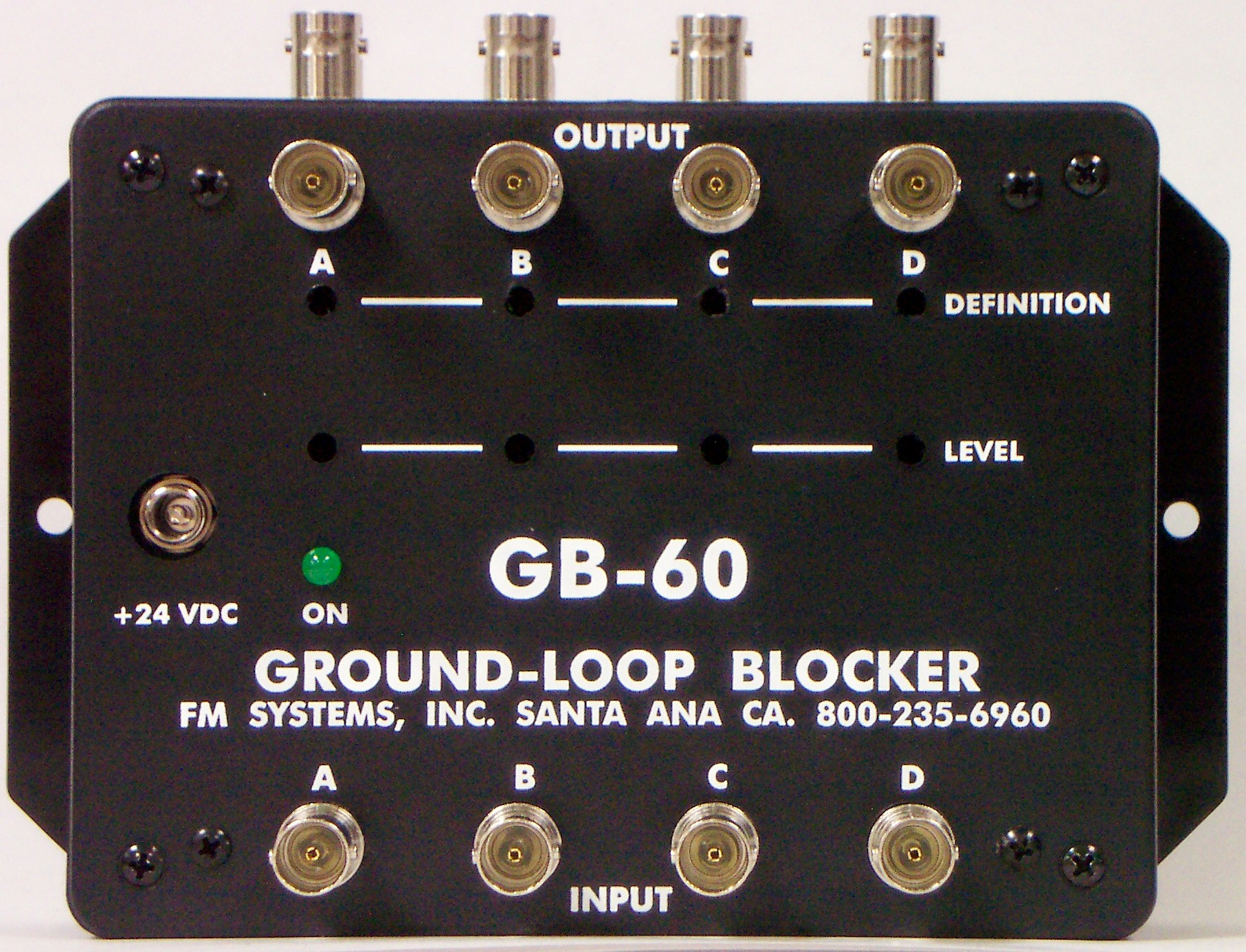
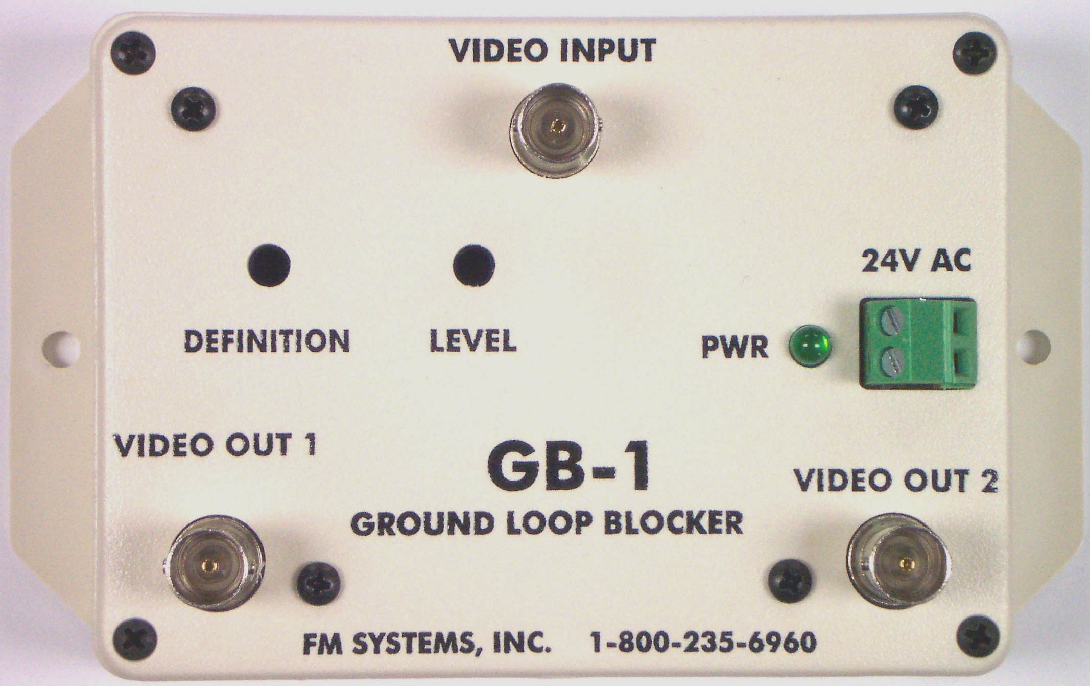
GB-60 for end of line compensation GB-1 for pre-boost and mid-point compensation. CLICK on the links to See More.