

PICTURE QUALITY TESTING OF CCTV SYSTEMS
PICTURE QUALITY TESTING OF CCTV SYSTEMS
Author: Frank McClatchie, FM SYSTEMS, INC. 1-800-235-6960
Picture quality can be defined by many different parameters, but the most important from an observed picture detail point of view is the LINES OF DEFINITION as observed on a Monitor. The larger the “number of lines” that can be distinguished, the greater the detail in the picture. The number of Lines of Definition actually has nothing to do with the number of horizontal lines that comprise the picture. In fact, all CCTV cameras used in the United States create exactly the same number of horizontal lines in the picture regardless of the Lines of Definition that the camera can produce. The term, Lines of Definition actually refers to the number of times the picture screen can be modulated (made lighter and darker) across the screen. Therefore a test pattern for this purpose would display vertical lines on the screen of the Monitor. Fifty white lines alternating with fifty black vertical lines across the screen would constitute a total of 100 Lines of Definition. The more lines that can be discerned, the greater the fine detail observable in the picture.
High picture definition would enable a viewer to clearly see as many as 500 or more “Lines” in each screen width. Medium definition would blur 500 “Lines” but would clearly show 400 or less “Lines”. Low picture definition would blur 300 or more lines, but clearly identify 200 or fewer “Lines” per screen width. To clearly identify the picture definition capacity of any specific CCTV system, a test pattern generator needs to be connected at the Camera location and the resulting test pattern observed at the Monitor location.
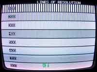
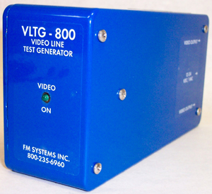
The VLTG-800 is a Video Line Test Generator that creates a normal NTSC video picture with a test pattern consisting of 100, 200, 300, 400, 500, 600, 700, and 800 “Line” groups. Each of these groups of “Lines” is clearly identified so that you do not have to count the lines on the screen. Monitors may be tested “on the bench” by connecting the VLTG-800 directly to the Monitor under test.
The “Lines of Definition” for that Monitor will be clearly evident on the Monitor screen. This test should be performed prior to any field tests of the CCTV system to make sure that the Monitor does not constitute the limiting factor in overall picture definition.
The ability of a Video Recorder to reproduce a picture without degrading picture quality can also be tested with the VLTG-800 by connecting it to the Recorder and Monitor, recording the test pattern and playing it back into the Monitor. Their should be no reduction in the “Lines” as played back into the Monitor.
If it is a Tape Recorder, old or worn tape will play back fewer “Lines” than new tape. Even new tape of different types may show variation in the number of “Lines” played back. Worn Tape Heads will also show fewer “Lines” than new Tape Heads. It is recommended that this test be performed at regular intervals to catch Tape Head wear before performance suffers.
After the Monitor and recorder have been proven to display at the desired quality level, a Camera is chosen that is capable of at least equal “Lines” capability. Now the entire CCTV system is assembled complete with the transmission system (whether coaxial cable, twisted pair wires, fiber-optic, or wireless) to see if the transmission system degrades the overall system performance. To perform a picture quality test of the complete CCTV system, temporarily replace the Camera with the VLTG-800 test generator. Now the test signal must traverse the transmission system (coaxial cable, twisted wire, fiber-optic, or wireless) as well as the receiving terminal equipment. The video losses encountered in the transmission facilities will degrade the number of “Lines” observable in direct proportion to the length and type of facility. Now compare the “Lines” observable through the entire system to that observed on the Monitor alone. If the “Lines” have been significantly reduced below the performance target because of the losses created by the transmission facilities, then it is time to consider applying amplifiers and equalizers to the system to bring it up to performance targets.
Loss of video level and the even much greater loss of high frequency resolution occurs on coaxial cable and twisted wire (UTP) facilities in direct proportion to the length and quality of those facilities. Serious loss of quality in terms of “Lines” can begin to occur in unequalized transmission facilities as short as 400 feet or less.
Finally, after the Monitor and Recorder have been proven to display at the desired quality level, overall tests can be made, including the Transmission facilities. To do this, temporarily connect the VLTG-800 in the place of the Camera and observe the number of “Lines” that are clear on the Monitor. If the number of “Lines” now observable is lower that the desired quality performance level, that condition can be cured by adding amplifier/equalizers to the transmission facility.
Twisted Pair (UTP) and coaxial cable equalizers can fully compensate for the loss of picture level and loss of “Lines of Definition” in cables up to about 4000 feet. Even greater distances can be equalized by adding intermediate “booster” amplifiers and equalizers. These cable equalizer/amplifiers are made by a variety of manufacturers, and when included in CCTV system designs can completely offset the cable or twisted pair loss so that the resultant “Lines” delivered are as good as the Camera, Recorder, and Monitor can produce “on the bench”. In effect, when a transmission facility is properly equalized, the transmission facility becomes “transparent” and will not degrade the picture that a given Camera, Recorder, and Monitor can produce.
The VLTG-800 becomes instrumental in adjusting the equalizers and amplifiers for optimum performance. It is not enough just to add some gain and equalization to the transmission facility. It is just as important to add the right amount of compensation. More compensation than is required is just as bad as none, or too little compensation. The VLTG-800 in conjunction with the CM-2 Camera Master makes it possible to correctly equalize any cable so that it becomes transparent to the video signal. To exactly compensate for cable loss, temporarily connect the VLTG-800 in place of the Camera and connect the CM-2 Camera Master in line with the input to the Monitor. With all of the equipment turned on and working correctly, observe the CM-2 (on the SYNC scale). Adjust the amplifier LEVEL control until the CM-2 reads 40 IRE Units. Next set the CM-2 to the COLOR BURST scale and adjust the DEFINITION control on the equalizer until the CM-2 reads 40 IRE Units on the color burst scale. When both SYNC and COLOR BURST read 40 IRE Units on the CM-2, then the transmission system is perfectly aligned to the optimal 40-40 condition and the transmission system is now transparent to the video signal. In this condition the transmission system will transmit the full capability that any Camera, Recorder, and Monitor can produce.
Using the VLTG-800 Video Line Test Generator as a test signal source and the CM-2 Camera Master as the picture quality measurement system enables a specific quality Proof of Performance to be performed on any new transmission. Component parts can be evaluated as to picture quality to isolate, identify, and replace non-conforming parts to upgrade CCTV system performance. In particular, the loss of “lines” caused by the coaxial cable or twisted pair transmission facilities may be completely compensated by using cable equalizer/amplifiers such as the GB-60, GB60-UTP, or GB-464 so that every CCTV system you install will have the best pictures possible.
For more information about cable equalizer/amplifiers contact FM SYSTEMS, INC. at: 800-235-6960 or 714-979-3355. FM SYSTEMS, INC. Santa Ana, CA.

