ELECTROMAGNETIC RELAY DEFINITIONS
ELECTROMAGNETIC RELAY DEFINITIONS
By: Don McClatchie
When designing or repairing electronic circuits that use electromagnetic relays a clear understanding of the important operational parameters of the relay can help you build a better project or help you to determine the reason for a failure. Let’s start with a look at the relay definitions so you can use the correct relay for your application and replace a relay with a similar one when needed. The definitions are divided into six groups, COIL, CONTACTS, PERFORMANCE, HIGH FREQUENCY CHARACTERISTICS, and RELAY TRICKS.
COIL:
COIL: The Primary, or Input has the following specifications.
COIL RESISTANCE: The DC resistance of the coil measured at a given temperature.
COIL DESIGNATION: There are several different types of coils like the Single Side Stable Polarized and non-Polarized, 1 coil latching type, and 2 coil latching types, with many different contact combinations. Polarized types are for DC and must have the correct polarization to operate properly.
PICK-UP VOLTAGE: The minimum voltage that guarantees the pull-in (transfer) and operation of all contacts.
DROP-OUT VOLTAGE: The maximum voltage that will guarantee relay release back to its non-energized state.
RATE COIL VOLTAGE or Nominal Coil Voltage is a narrow range of voltage or single value designed to energize the magnetic coil.
MAXIMUM CONTINUOUS VOLTAGE: The maximum voltage that can be applied continuously without damage to the coil.
NOMINAL OPERATING CURRENT: The amount of current that flows when the relay is activated with the normal operating voltage.
NOMINAL OPERATING POWER: The value of power used by the coil when it is energized by a normal voltage. Measured in Watts (W) for DC coils and volt amperes (VA) for AC coils.
CONTACTS:
CONTACT FORMS: The most common are Form A, Form B, and Form C. The Form A is Normally Open, Form B is Normally Closed, and Form C is a change over from Normally Open to Normally Closed contacts.
CONTACT RESISTANCE: The total resistance measured by voltage drop across the contacts, terminals, and contact springs.
RATED SWITCHING POWER: This is the designed value in watts (DC) for (VA) for AC that can be safely switched with the contacts.
MAXIMUM SWITCHING VOLTAGE: This is the maximum open circuit voltage that can be safely switched.
MAXIMUM SWITCHING CURRENT: This is the maximum current that the contacts can safely switch.
MAXIMUM CARRYING CURRENT: This is the maximum current that the contacts can handle without being damaged by over temperatures in the relay.
MINIMUM SWITCHING CAPABLILITY: This is the minimum value of voltage and current that can be reliably switched and are controlled by the material used in the contacts of the switch.
MAXIMUM SWITCHING CAPACITY: This is derived from the maximum voltage and current for the relay.
MBB CONTACTS: This is an abbreviation for “Make Before Break”. It means that one set of contacts connect before the other set of contacts separate and can only be done with Form C contacts.
TERMINAL CAPACITANCE: The value measured between the terminals with 1kHz at 20 degrees C.
PERFORMANCE:
SET TIME: This describes the operating time required for a bi-stable or latching relay.
RESET TIME: This describes the release time required for a bi-stable or latching relay.
VIBRATION RESISTANCE, DESTRUCTIVE: The maximum vibration that the relay can handle without a change in the operating characteristics measured in “G”s and frequency range.
VIBRATION RESISTANCE, FUNCTIONAL: The maximum vibration that can be tolerated without causing a contact to open for a specified length of time.
INSULATION RESISTANCE: The resistance measured between all the mutually isolated conduction parts of the relay as in the coil and contacts, across open contacts and between coil or contacts to any core frame material at ground potential. Also known as Initial Insulation Resistance.
BREAKDOWN VOLTAGE: This is the Hi-Pot or Dielectric Strength, the maximum voltage that can be tolerated by the relay without damage over a specified time.
SURGE WITHSTAND VOLTAGE: The ability of the relay to withstand abnormal externally produced power surges, specified by a graph of rise time, peak value, and fall time.
OPERATE TIME: Also known as Pull-in or pick-up time, the time from the application of power to the closure of all normally open contacts not including bounce time.
RELEASE TIME: The time measured from power removal to the opening of all contacts that are normally open not including bounce time.
RELEASE BOUNCE TIME: The time measured after release until the contact bounce has ended.
SHOCK RESISTANCE, DESTRUCTIVE: Physical force expressed in “G”s required to damage or alter the relays characteristics.
SHOCK RESISTANCE, FUNCTIONAL: The maximum acceleration force that can be applied without causing a contact to open for a specified length of time.
MECHANICAL LIFE: The minimum number of times the relay can operate normally with no load on the contacts.
ELECTRICAL LIFE: The minimum number of times the relay can operate with a specific load being switched by the contacts.
CONTACT BOUNCE TIME: The time measured in msec (milli-seconds) that a contact requires to stop bouncing from the initial contact.
MAXIMUM SWITCHING FREQUENCY: This refers to the maximum switching frequency applied to the coil that will meet all the specifications of the relay.
LIFE CURVE: Is the contact “number of operations” and is determined by the switching voltage and current used and the type of load resistive or inductive.
HIGH FREQUECY CHARACTERISTICS:
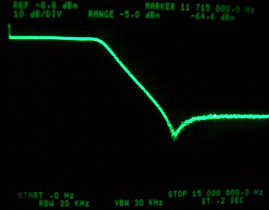
High frequency signals will leak through stray capacitance in the contacts and insulation materials. This leak is called isolation loss and is expressed as dB loss. There is also Insertion Loss at high frequency caused by self-induction, resistance, and dielectric loss including signal reflections due to impedance mismatching in circuits. Any, and all of these will create Insertion Loss and degrade any high frequency AC signal. V.S.W.R. (Voltage Standing Wave Ratio) is affected by high frequency resonance generated by interference between the input signal and reflected (wave) signals.
RELAY TRICKS:
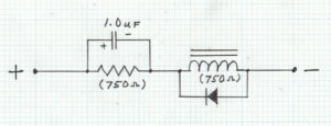
OPERATING CURRENT REDUCTION: For battery operated devices or circuits that need to lower current requirements, there is a method for reducing the current use for any relay circuit. This circuit takes advantage of the difference between the “Pick-Up” voltage and “Drop-Out” voltage in an electromagnetic relay. As an example, for a common 12 VDC relay the minimum Pick-Up voltage may be 8.4 VDC but the maximum Drop-Out voltage is 1.2 VDC, this difference can be exploited to operate the relay at a much lower voltage and so reduce the holding current required for the relay.
If you were to place a resister equivalent to the coil DC resistance in series with the coil of the relay to reduce the voltage across the coil to just above the Drop-Out voltage required to hold the relay closed, in this case half the normal voltage, your relay would use half the current to stay in the closed position. However, that amount of current/voltage might not operate the relay reliably. The next step is to add a capacitor say 1 microfarad across the series resistor to create an impulse boost of the voltage across the coil when the relay is energized. The capacitor causes the leading edge of the initial pulse to peak up into the range of voltage that will allow the relay to pull down and when the capacitor is fully charged the current will drop back to the low level used to hold the relay down without the extra current.
In this way the holding current can be reduced dramatically while still generating the Pick-Up voltage required to operate the relay reliably. This approch can affect the relays “OPERATE TIME, and VIBRATION RESISTANCE,” because of a reduced magnetic field holding down the contacts, but in most applications, it will not be noticeable. The capacitor size must be large enough to create a momentary impulse to match or exceed the “OPERATE TIME” to be sure to reliably pull down the relay. If you have a product that draws a lot of current or needs to shed some heat due to heavy currents for relays, this trick works very well.
SHARING RELAY CURRENT: If you have a product with a relay and an LED Light Emitting Diode that turns on when the relay turns on you can put the LED in series with the relay coil and share the current and light the LED for free. The trade off is that you must prevent Counter EMF Electro-Motive-Force the high voltage generated from the collapse of the coils magnetic field from damaging the LED. This can be done with a diode placed across the coil terminals in parallel with the coil windings in the opposite direction of the current flow. A diode should be placed there anyway as a precaution to prevent high voltage spike from damaging other components in the circuit. The other trade off is the loss of terminal voltage due to the two forward diode drops in the LED.


