WHAT IS VOLTAGE DROP? and WHAT CAN YOU DO ABOUT IT?
WHAT IS VOLTAGE DROP, AND WHAT CAN YOU DO ABOUT IT?
By: Frank McClatchie
Every CCTV installer has experienced this phenomenon when running long wires to power a camera or other devices. The voltage delivered to the camera is never the same as the voltage measured at the power supply location. There are several factors that affect this voltage drop, so it’s no wonder that there is so much confusion about voltage drop in CCTV systems. To start with, there are actually two different kinds of voltage drop involved in every camera installation. Unless you consider the two different kinds of voltage drop, your camera power supply may fail to perform as expected.
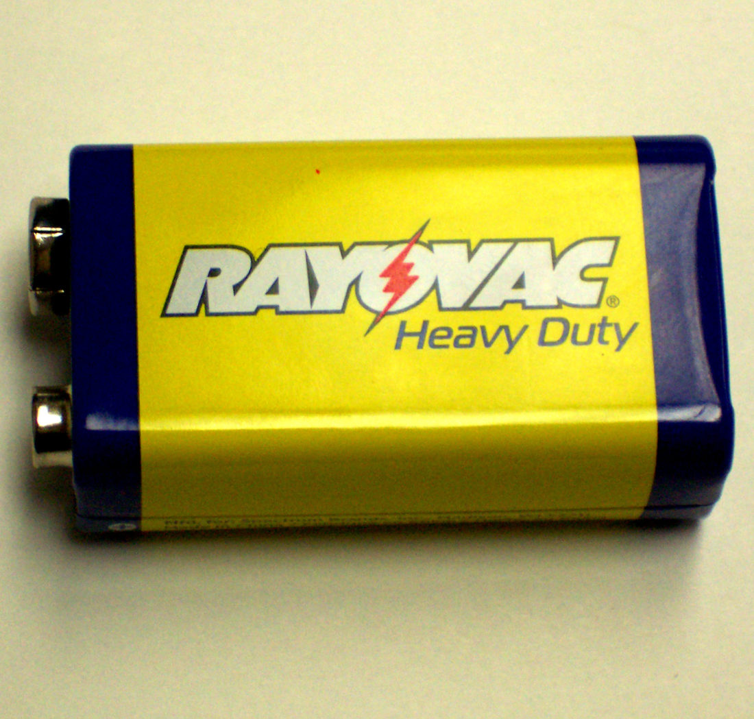
So what is voltage drop? One of the first examples that come to mind when considering voltage drop is the example of testing a nine volt battery. Of course it almost always measures a full 9.3 volts. But is it fully charged? There is no way of knowing until a voltage measurement is made while the battery is under full load. The only legitimate way to test that nine volt battery is when it is connected to the equipment it is supposed to operate. When measuring the voltage of a battery under load you may find that the voltage has dropped considerably from what was measured when the battery was disconnected. Always measure the battery voltage at full load. The same thing goes for measuring CCTV supplies. Never measure the open circuit voltage at the camera location, always make sure that the camera is connected and fully operational when measuring the voltage at the camera.
Cameras on the market today have a relatively narrow range of voltage over which they will perform satisfactorily, and just raising the voltage at the camera may not work either, because applying too high a voltage to the camera will result in the camera manufacturer canceling the warranty on the camera and excess voltage at the camera can lead to over heating and premature failure of the camera.
There are actually two voltage drops to be considered when installing CCTV system.The first voltage drop to consider is the voltage drop that can occur at the power supply location when any load is applied to the power supply. Unregulated power supplies (generally the least expensive ones) will usually suffer with a greater voltage drop than a “Regulated” power supply. In addition unregulated power supplies will have an output voltage that varies with changes in the main power line voltage and will alter the voltage applied to the camera as well.
Check the ratings of your power supply for voltage under load vs. open circuit voltage. Generally speaking, the greater the load applied to the power supply, the lower the output voltage will be under load.
A well regulated power supply will deliver pretty much the same voltage at the power supply output as long as you do not exceed the current limits of the supply, however the voltage delivered to the camera must pass over a pair of wires in order to get to the camera.
The second voltage drop is the most limiting factor in any CCTV Camera system and it is the primary limiting factor in power delivery. This second voltage drop is caused by the resistance of the loop of wire connecting the camera to the power supply. The resistance of the loop of wire connecting the camera to the power supply impedes the current flow and is the cause of the second kind of voltage drop. The distance a camera can be placed from a power supply can be doubled by doubling the number of wires being used to deliver power to the camera or by increasing the diameter of the wire and thereby reducing the voltage drop accordingly.
PRACTICAL FACTORS THAT SET THE MAXIMUM CAMERA RANGE.
Although the distance a camera can be located from a recorder has no particular limit, there are some practical factors at work that limit the economic range for power distribution between the camera and recorder. We will refer to this limit as CAMERA RANGE in this discussion.
CAMERA RANGE is defined in terms of the maximum number of feet of cable that are required to reach the camera from the location of the Power Supply, including all the zigs and zags necessary to get to the camera location.
The essential limit that sets this maximum distance is the loop resistance of the wire being used to connect from the power supply to the camera. Some cameras require Direct Current (DC) while others will operate from Alternating Current (AC) and the limits of the voltage and the current required to drive the camera vary accordingly.
To calculate a maximum CAMERA RANGE for any particular equipment, it is necessary to consult the manufacturer specifications for the equipment. Certain factors are critical to this evaluation.
They are:
1. The Voltage output of the power supply without any load = ? Volts.
2. The Voltage output of the power supply under full load = ? Volts.
3. The current available from the power supply = ? Amperes or milli-Amperes.
4. The maximum input voltage to the camera = ? Volts.
5. The minimum input voltage to the camera = ? Volts
6. The maximum current drawn by the camera = ? Amperes or Milli-Amperes.
Factor 4,5, and 6 determine the second kind of voltage drop limitation. Factor number 2 the Voltage output of the power supply under full load must exceed Factor number 5 or the system will not function correctly. Subtracting Factor 5 from Factor Number 2 will determine the maximum CAMERA RANGE available. Record this voltage for future reference. This is the greatest voltage drop that the system can tolerate and determines the distance a camera can be placed from the source of power.
It is a wise procedure to document all six of these numbers somewhere, so that at a later date they can be consulted to see whether additional cameras can be added and what the CAMERA RANGE is on any given type of installation.
CAMERA RANGE can be extended by using multiple pairs of wires, or larger gauge wires on any given installation doubling the number of wires will double the CAMERA RANGE, and tripling the power delivery wires will triple the CAMERA RANGE and so forth. Also going to a larger wire size does the same thing. Consult the wire gauge table to see how much additional CAMERA RANGE can be obtained in each wire size. HOW WIRE GAUGE EFFECTS CAMERA RANGE.
As the diameter of the wire used increases so does the CAMERA RANGE. For instance, if the wire gauge is increased from 22 gauge to 20 gauge the CAMERA RANGE is increased by 59 percent, while increasing the wire size to 18 gauge will expand the CAMERA RANGE by 153 percent.AN EXAMPLE OF A TYPICAL CAMERA RANGE CALCULATION.
Let us say that the power supply is capable of supplying sufficient current and has a minimum voltage output sufficient to drive the camera and the voltage drop induced by the connecting power wires.
By subtracting the minimum input voltage that the camera will operate at from the minimum voltage that the power supply will generate, we get the voltage that can be utilized to overcome the resistance of the wire connecting the power supply to the camera. This voltage drop can be directly converted to the maximum permissible CAMERA RANGE.
This mathematical computation will give a precise answer to the maximum number of feet of power delivery wire that can be placed between the camera and power supply. The mathematical computation follows:
The CAMERA RANGE = LOADED POWER SUPPLY VOLTAGE MINUS the MINIMUM CAMERA VOLTAGE, TIMES the WIRE GAUGE FACTOR. The answer to this equation is the maximum number of feet that a camera can be located from the power supply. This includes all the zigs and zags necessary to reach the camera from the power supply. If a shorter route from the power supply to the camera can be found, then so much the better.
The WIRE GAUGE FACTOR for different wire gauges is as follows:
STANDARD
WIRE GAUGE WIRE GAUGE FACTOR COMPARE WITH 22 GAUGE
16 124.5 4.02 X
18 78.31 2.53 X
20 49.26 1.59 X
22 30.99 1.00 X
24 19.47 0.629 X
26 12.25 0.396 X
The “Comparison with 22 Gauge Column” in the table enables a comparison between the different wire gauge sizes in terms of the relative number of feet that a camera can be placed from a recorder. This clearly indicates the relative advantages of utilizing larger gauge wires to supply power to cameras. For any particular manufacture of cameras and power supplies, a particular limit in feet between a camera and power supply exists, limited by the difference in voltage between the minimum power supply voltage delivered to the load and the minimum input voltage for the camera. This constitutes the maximum CAMERA RANGE measured in feet between the power supply and camera using a particular wire gauge to deliver the power to the camera.
MAXIMIZING THE AVAILABLE “CAMERA RANGE”
When choosing a camera for a CCTV system wherein a common power supply will be used to power the cameras through pairs of power delivery wires you will want to increase the CAMERA RANGE as much as possible by examining the minimum output voltage under full load of the Power Supply to be used to the highest voltage possible that does not exceed the maximum voltage permitted at the input to the cameras, and the lowest input voltage a camera will operate correctly at.
This difference between the output of the power supply compared to the minimum voltage of the camera is the maximum voltage drop the system will sustain, The maximum Camera range will then be the Voltage drop times the WIRE GAUGE FACTOR shown in the table. This computation then will derive the maximum CAMERA RANGE, as measured in feet between the power supply and the camera for each wire gauge that may be used to supply power to the cameras.
The maximum camera range in feet is simply the voltage drop permissible in the systems times the WIRE GAUGE FACTOR.


