

TV AUDIO DEVIATION: MEASURING AND SETTING IT
TV AUDIO DEVIATION:
MEASURING AND SETTING IT
Measurement and control of TV audio volume has always been with us, but other concerns have usually taken precedence. Loudness contrast between channels is accentuated by program source switching and local ad insertion, not to mention audio volume changes with each new program on any given channel. This paper explains why two programs of equal peak deviation can have very different loudness; how to measure “loudness;” how to adjust TV audio modulators to equal loudness on each channel; and how to keep loudness constant even though the source program volume changes. First some theory, then the practical art “equalizing” audio levels.
Peak factor
The peak factor of an audio signal is herein defined as the ratio between the peak voltage and the RMS voltage in the particular waveform being observed. This is usually expressed in dB. Thus a square wave has a o dB peak factor, since the peak and RMS voltages are equal. A sine wave has a 3 dB peak factor since the peak voltage exceeds the RMS voltage by 1.414 and 20 log 1.414 = 3.01 dB. Natural voice or music waveforms can have peak factors ranging from 13 dB to 17DB. “Single talkers” tend to have the highest peak factors, with certain languages and talkers ranging up to the 17 dB level. Multiple musical instruments and combined voices (such as singing) tends to reduce the peak factor to about 13 dB.
Well, if most natural audio has a 13 dB peak factor, why does the audio industry refer to a standard 10 dB peak factor? Because almost all testing is done with sine waves that have a 3 dB peak factor! Thus we are referring to the difference between the 3 dB sine wave ad the 13 dB music peak factors.
All of the foregoing discussion refers to natural voice or music. In practice, these numbers will vary according to the degree of peak clipping and/or compression applied to the natural audio prior to transmission. Note that the FCC defines frequency modulation (FM) in terms of a deviation limit, which is directly proportional to the peak voltage of the modulating waveform. However, the human ear perceives loudness as a power-derived factor, which relates to the RMS value of the modulation waveform. Since the broadcaster has a natural interest in producing the loudest audio possible without exceeding the FCC deviation limits, the industry has expended considerable effort and ingenuity to compress the peak factor even more while still not increasing distortion excessively.
Of course, it could be said that any change in the waveform constitutes technical distortion, but what is important to the broadcaster is perceived distortion. Thus it comes to pass that some broadcasters (and recording studios) are far more aggressive in peak factor reduction than others. As a result, any two program sources that exhibit equal peak deviation can be very different in perceived loudness.
A good practical example of differing peak factor compression resulting in loudness differences can be found on your FM dial. Tune in a “Classical” station, then a “rock” station. They are both modulating ±75 kHz, but the “classical” station will sound much weaker, even during a loud passage.
Practical Implementation
While all of the foregoing leaves us with program of varying loudness, the sub still will complain if the volume changes more than he or she perceives as acceptable. No standard fits all subscribers in how much is acceptable. The only thing that will reduce complaints to a minimum is to reduce volume differences below the level of audible perception. One deciBel is ordinarily conceded to be a just-perceptible level change, so if we can hold average level differences between channels and between successive programs to the order of ±1 dB or so, we can hope to reduce this source of subscriber complaint to a minimum.
Off-air channels usually have their audio carefully controlled and so should not require further control at the headend. This is fortunate since most off-air signals are I.F. converted and cannot be controlled without going to baseband conversion. In fact, since these channels tend to have constant volume and can’t be controlled in most systems anyway, these are usually the “reference channels” to which the volume of other channels are adjusted.
Ad insertion channels are prime candidates for program audio level control. The same ad videotape will play back at differing loudness on different VCRs and obviously tapes recorded at different times and locations also vary in volume.
All of these combinations tent to be different from the preceding program material. All channels carrying local advertising should be equipped with audio ALC systems between the ad-insert equipment and the TV modulator (not just within the ad-insert equipment).
Program switching between different sources very often results in severe volume changes. An audio ALC system should be placed between the program switches and the TV modulator.
Local origination audio is very difficult to control and usually requires an operator, but he or she is busy enough with the video, so often the audio volume changes more than it should. An automatic audio ALC system would exert this control and thus keep this channel under control.
In additional to the preceding group of channels, that are on the “must control” list, you may find that some other program sources should be added to the “controlled” list.
The conundrum
Now, if we are to placate the subscriber, we must either re-process all incoming audio to the same peak factor and so have equal loudness, and equal audio deviation, or we can accept audio as we find it, but set the audio volume to be constant between channels and let the deviation fall where it may (within reasonable limits). Since the cable operator is not constrained by the FCC in the same way that a broadcaster is, the cable operator can adjust his deviation over ±25 kHz for under-processed audio and under ±25 kHz for aggressively processed audio.
The “old-fashioned way” to set equal loudness is to let your ear decide by switching between channels. This is very time consuming and pretty frustrating because the ear has very poor loudness memory. The ear is pretty good for comparing on an A/B basis, but since the two programs are not necessarily at 100 percent modulation at the same time, much time is lost waiting for volume peaks on both in quick succession.
As we have already seen, neither peak deviation (as measured on a storage spectrum analyzer), or peak voltage measurement (as measured by “peak flasher” or peak reading voltmeters) will measure comparative loudness between audio waveforms of differing peak factors. The only measurement that comes close to the human ear perception of volume is the RMS measurement. An ordinary RMS reading voltmeter will do this, but it still required considerable interpretive skill to read, since the operator must establish just what “peaks” to read. If it is an analog meter, this difficulty is compounded by the mechanical time constants and dynamics of the meter. If it is digital, reading the flickering numbers is literally impossible. The numbers is literally impossible. The RMS reading meter must record and store the highest RMS reading over the testing interval to be practical, for it is the highest (or 100 percent modulation level) that should be recorded, not some lower intermediate level that may be on part of the time.
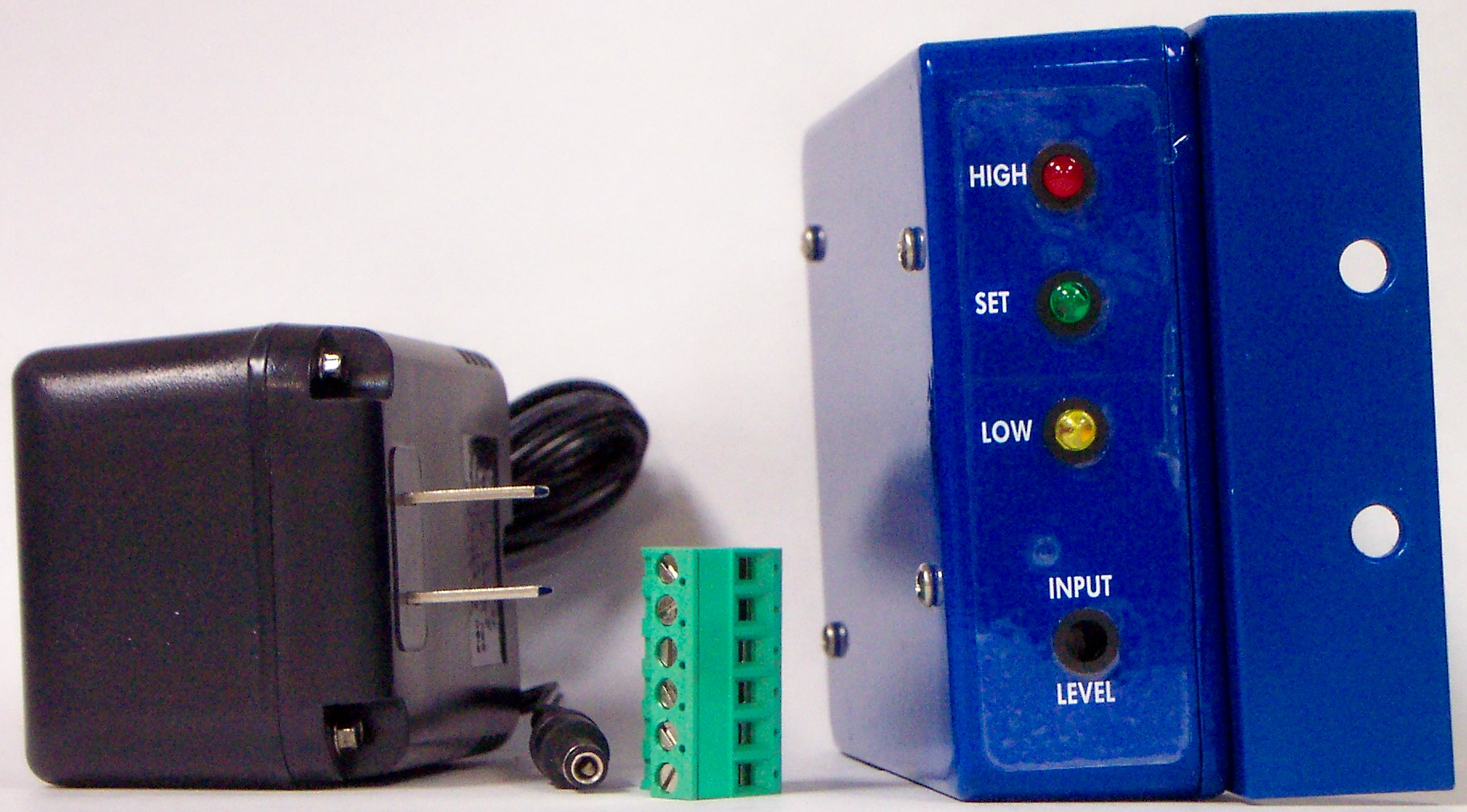
It does little good to measure the audio going into the TV audio modulator even with the digital RMS storage meter that was just postulated. To compare one channel with another, the digital RMS storage meter should be connected to the audio output of a TV tuner. Such a meter is available today1. It is called the ADM-1.
Keeping loudness constant
Now that we know how to equalize the volume on the channels that we can control, how can we keep them from changing during ad inserts, program source switching, and other sources of volume changes? The answer is automatic audio level control applied between the audio source (such as the satellite receiver) and the TV audio modulator. This requirement is especially acute on the new BTSC stereo modulators, some of which have an audio control system built-in. A number of audio automatic level control systems (ALC) are available today from such manufacturers as Circuit Research Labs, Leaming Industries, FM Systems Inc., Aphex Systems Inc., Orban and Scientific-Atlanta. Some are elemental in operation, while some are quite sophisticated. Just what can a sophisticated ALC do that it’s more elemental brother cannot do? Whey buy the fancy model?
Audio ALC systems range from simple automatic variable gain devices to complex systems that control the gain in such a way that the listener is not aware that control is being exerted.
The simple ALC control system will maintain a constant audio output, but with certain rather obvious “control artifacts” such as: 1. “Noise pumping.” This is heard as a rushing hissing noise gradually increasing and decreasing in amplitude as the program volume changes. This hiss can be really objectionable during long pauses between normal program levels. 2. “Ducking.” The sudden reduction of ordinary background sound following a sudden loud sound, such as a gun shot. 3. “Program pumping.” This is caused when intermittent high level low frequencies such as bass drums or other low frequency pulsing sounds modulates the volume of mid- and high-frequency sounds. This can be particularly noticeable and objectionable on certain program content.
Sophisticated ALC systems
These more complex ALC systems deal with these control artifacts with varying degrees of success. The best of them give no audible clue to their operation, except that the audio level stays substantially constant over a wide range of input levels. Characteristics to look for when searching for a very good audio ALC: 1. “Gating.” A good gating system will prevent noise pumping. The gate locks the gain setting upon a sudden reduction of audio level, like a pause in speech. A good gate will not permit the gain to change until program audio returns. Since the gain is prevented from increasing during pauses, noise cannot be pumped up. 2. “Program-dependent gain control.” This feature, when properly implemented, will prevent ducking. Sudden very loud noises will not change system gain, while longer term loud passages will exert gain reduction to maintain ca constant output level. 3. “Dual-band control.” By splitting the audio band into two parts, the low frequencies can be separately controlled from the high band, therefore intermittent high level low frequencies cannot modulate the volume of the higher audio frequencies, thus preventing program pumping.
Artful implementation of these three aspects of the automatic level control system can control audio level to very close tolerances even with input level variations of 30 dB, and do so with no perception on the part of the subscriber that any control is being exerted. In effect, a very good ALC system acts just like a tireless professional audio operator on the job.
Over the years, TV audio has almost been a “necessary evil”: Necessary for obvious reasons, and evil because really good control systems were absent and there were may other more pressing problems to solve. Cable has grown and with that, subscriber expectation of professional grade video and audio.
By Frank McClatchie, FM Systems Inc.
1988 with permission from the NCTA
Technical papers, 1988