SDI VIDEO GROUND LOOPS THE SILENT EQUIPMENT KILLER
By: Don McClatchie
The SDI video camera has emerged as a popular way to use existing CCTV cables once used for analog cameras, to transmit a digital high definition camera images. As the use of these SDI cameras expand a problem has emerged that if gone unchecked can destroy the SDI camera and the DVR over a short length of time. If you have had an SDI camera fail in just a few weeks or months after installation or you are going to start working with SDI cameras, this article will help to explain SDI video ground loops and why the camera fails and how to avoid early failure on your next installation. For the most part SDI signals are immune from showing any sign of ground loop artifacts on the video image because the signal is digital and so you will not see any problems with image quality until the signal fails completely. However if you do have a ground loop at work in your installation, it can be slowly destroying your equipment and worse it can lay in wait to strike your equipment when a random power surge takes place.
First of all, what is a ground loop and how is it formed? The source of the ground loop originates from the power industries use of local grounds to balance their power grid. Everywhere 60 cycle power is used, a local ground is attached to the power grid to return all unbalanced current flow to ground. As an example, you will notice that every main power breaker box will have a ground wire or conduit going to a ground rod or similar device connected to an earth ground. Every correctly installed power outlet will have a connection to this ground. Not all grounds are created equal. In fact the earth ground in one building is most likely to have a different voltage potential relative to any other building, even grounds inside the same building will have different voltages between them, based on the uneven current flow of the power load.
Here is how the ground loop gets onto your SDI signal. If you connect a coaxial cable to an SDI receiver or other equipment that plugs into the 60 cycle main power and the other end of the coaxial cable becomes grounded locally for any reason a Ground Loop path is created. Any difference in the 60 cycle voltage between these two ground points will create a current flow in the shield of your coax cable that induces the 60 cycle AC voltage directly into the SDI signal. Keep in mind that the ground loop interference will not be seen on the SDI video image but it can do some serious damage to your equipment over time, how much time is dependent on how much ground loop voltage you have in your signal.
Here is what causes the damage to your equipment over time. The ground loop voltage originating from the power system in the building flows down the coaxial cable and into the terminations in the SDI equipment. There are two different types of terminations used in SDI equipment. The signal originating equipment like a camera has a “Source Termination” 75 Ohm resistor in series with the output signal driver, this launches the signal down the cable with the proper 75 Ohm impedance to match the cable.
The second type of termination is the one most installers know about called the end of line termination that is also a 75 Ohm resistor connected from the center conductor to the ground shield to absorb all of the signal energy and prevent reflections that cause interference in the signal. With SDI equipment both of these terminations are normally built into the equipment and are not accessible to the installer.
These terminations are designed to take the normal 800 millivolt SDI signal and dissipate that energy as heat in the 75 Ohm resistors. However when you have a large ground loop voltage on your signal anything above 2.7 volts, these resistors can be overheated beyond their rating to the point of destruction over time, they will slowly cook and burn away the resistive element causing them to eventually go open circuit preventing the signal from being delivered. It is a silent equipment killer because when this is happening you will have no indication from the digital video signal that anything is going wrong. This kind of slow cooking of the terminations causes the equipment to eventually go intermittent for a time and then fail completely.
Also when you have a ground loop path any spike in the ground differential voltage can cause an instantaneous ground loop voltage spike of many hundreds of volts that can fuse open these terminating resistors and cause immediate and permanent failure of the system. This kind of failure will not go intermittent before total failure. It just fails immediately after the power spike.
If you suspect you have a camera with source impedance damage you can test the source impedance inside the camera by using a meter like the SDI-2 and measure the signal level coming out of the camera then externally terminate the SDI signal with a 75 Ohm terminator. If the signal level drops by exactly 6 dB then the internal source termination is good, however if it does not drop by that exact amount then you will know that the internal source impedance resistor has been damaged and by reading the amount of drop or lack of drop you can determine the actual resistance of the source termination and the degree of damage sustained. The SDI-2 test meter is a good low cost tool for anyone working with SDI signals. Use it to measure SDI signal levels, check existing analog cables for SDI use, and with an optional inline filter check for cable slope loss. It reads the level in dBm and relative Millivolts Peak to Peak.
Now that you know what causes the damage to your equipment, how can you prevent it from happening to you? The first thing to do when you are installing SDI cameras is to check for ground loops before you leave the job. The ground loop is a differential voltage measurement.
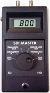
It is easy to measure these differential voltages, simply disconnect the video cable at one end only and using your voltmeter on AC volts, then put one probe on the shield of the video cable and the other probe on the SDI connector outer shield on the other equipment, you will be amazed at the difference. Any voltage that exceeds 0.1 Volt can be a problem for you in the future. We also have a meter called the SDI-1 that has additional features for measuring SDI levels in dBm, cable equalization in dB, termination resistance in Ohms, and ground loop measurements in volts.
The solution is to never connect both ends of an SDI cable to local grounds. Any cable can be grounded at one end without inducing the ground loop current. When you run coax cable from one building to another, it is acceptable to install through connection points, but do not allow the shields to come into contact with one another or the local ground. Any coaxial connector lying in a cable tray or conduit box can accidentally contact to ground and cause an unintended connection to ground, don’t let this happen. Use tape on the connector to prevent accidental grounding. Also try not to attach the camera to any structure that is likely to be grounded. Remember that the camera gets its ground from the opposite end of the coaxial cable by the monitor equipment. Be sure to incorporate a ground loop test on every SDI camera you install to prevent early failure of the equipment and the service call back.


