WHY ARE MY PICTURES FUZZY ON LONG CABLE RUNS?
By: Frank McClatchie
FM SYSTEMS, INC.
The culprit is the cable connecting the Camera to the Recorder. It is just that simple, but an actual description of the process that introduces this loss is a little more complex. This loss of picture detail or “pictures fuzzy” is actually caused by four factors that are involved with the physical construction of the cable. The same principles cause the problem whether the transmission cable is of Coaxial or Unshielded Twisted Pair (UTP) construction.
Here are the four main factors that determine this loss in any type of cable. First is the resistance of the conductors that make up the cable. This turns out to be very important for the CCTV operator. There are two general types of RG59/U cable on the market today. One type of cable is used by the CATV (Cable TV Industry) to transmit the much higher frequency TV Channels. That type of coaxial cable is used in higher quantity than CCTV coaxial Cable and is often lower in price than the RG59/U cable used by the CCTV Industry. From the outside the two cables look very much alike, and are frequently purchased by CCTV installers for camera picture transmission because the cable is cheaper to purchase.
This choice of cable turns out to be a serious mistake when the RG59/U CATV cable in used to transmit CCTV Camera pictures. The reason for this problem is that the center conductor and shield of the CATV type of RG59/U cable is actually made of copper-plated STEEL, and not pure COPPER. The CCTV type of RG59/U must be made of pure copper to keep the resistance of the center conductor and shield as low as possible to reduce the loss of the cable to the much lower video signal frequencies.
The CATV type of RG59/U can use a steel center conductor and shield because the very high frequencies of the CATV signal travel only on the outermost surface of the conductors which is actually copper plated to reduce losses at very high frequencies. Using steel conductors makes that type of cable cheaper to build than the copper cable intended for use on CCTV systems. Copper is much more expensive than steel. Even copper conductors have some loss, and that is why larger diameter cables tend to have lower loss, because the overall “Loop Resistance” of the larger diameter cable is less than the smaller cable, and therefore the loss will be less also. As a general rule of thumb, the larger cable will exhibit less loss than the smaller cable, but usually is much more expensive. Some metals have even lower resistance than “oxygen-free” pure soft copper, but are generally very expensive and are rarely used except in laboratories.
The second factor that determines the loss of a cable is the spacing between the center conductor and the shield of the coaxial cable, or the spacing between the wires for UTP cable. This is influenced by the spacing between the conductors, and also the material used as insulation to prevent the conductors from shorting out. The third factor that determines the loss of a cable is the type of insulating material used. The insulating material multiplies the capacity by a relatively large factor depending on the actual material used. The capacity between the conductors per foot of cable length is a primary consideration in determining the loss of the cable at video frequencies.
The RG59/U type of cable uses Polyethylene insulation that has a Dielectric Constant of 2.3. Other types of insulation between the center conductor and the shield generally will have a different Dielectric Constant, and thus a different capacity per foot of length and also a different amount of loss per foot. The lowest loss cable uses no insulating material at all, except for mechanical support, a simply gas or vacuum separates the two conductors. A vacuum will exhibit the lowest capacity and the lowest loss possible, but it will be very expensive and not practical. Some RG/U coaxial cables use a foam Polyethylene, and are a lower capacity and loss per foot, but the foam insulation is usually only used on CATV type of RG59/U type of coaxial cable.
The fourth factor that determines the loss of a cable is the total Inductance of the conductors in the cable. This inductance is primarily influenced by the diameter or cross section of the conductors. The lower the inductance per linear foot of cable, the lower the loss of video signal traveling down that cable. Since the diameter of a cable is determined by the diameter of the conductors, the larger cables the lower the inductive loss of that cable.
The manufacture of cable is a not quite that simple. Another very important factor besides the first four described above, involves dimensional accuracy and consistency in production. Any repeated variation in dimensional accuracy can also result in wild variations in cable loss at specific frequencies. This can seriously affect the overall frequency response of the cable and also affect the picture quality. This is particularly true of digital signal transmission where the repeated dimensional cable variations can result in an increased digital bit-error-rate that can wipe out the picture. That is the main difference between CAT 5 and CAT 6 UTP Unshielded Twisted Pair wires. The CAT 6 cable twist rate and wire separation is controlled more accurately in manufacturing process than it is in the CAT 5 or lower grade cables. If the Rate of Twist varies along the length of the cable in a regular pattern, a very deep loss at certain frequencies will occur that can strongly affect digital transmission and also analog picture transmission to a lesser extent.
The capacity per foot and the inductance per foot of the coaxial cable determine the loss of the cable at video frequencies and also determine the characteristic impedance of the cable. Most cables are designed to operate at either 50 Ohm impedance or 75 Ohms. There are other characteristic impedances, but the vast majority of coaxial cables are either 50 Ohm or 75 Ohms. The characteristic impedance is determined by dividing the inductance per unit length by the capacity per unit length and then taking the square root of that ratio. The characteristic impedance is therefore determined by the cross section dimensions of the center conductor, the outer shield and the Dielectric Factor of the insulating medium between the center conductor and the shield. Since the insulating medium can vary between 1 for a vacuum and 3 or more for certain types of plastics the impedance will vary as the square root of that Dielectric Factor. The Dielectric Factor is 2.3 for Polyethylene which is the most common insulating material for coaxial cables. It can be seen that both the Characteristic Impedance and Video Loss is heavily dependent on the type of insulating material.
Many cable specification sheets do not indicate what the inductance per unit length is, so there is another way to determine the Characteristic Impedance of a cable. This method requires knowledge of only the outside dimension of the center conductor, the inside dimension of the outer shield, and the Dielectric Factor of the insulating material between the center conductor and the shield. The formula is as follows:
Z = 90.99 X log D / d
Where D is the inside diameter of the shield, and d is the outside diameter out the center conductor.
This formula includes the Dielectric Factor of 2.3 for the polyethylene insulation between the center conductor and the shield. Except for the steel verses copper center conductor for the CATV and CCTV industries, the RG59/U with a pure copper center conductor type of cable is well standardized and quite reliable for the use of transmitting video pictures in the CCTV Industry.
There is one more problem associated with the use of RG59/U cable for CCTV picture transmission purposes that must be taken into consideration. BNC connecters are manufactured in two different ways. There is a 75 Ohm type of connector for video picture transmission, and a 50 Ohm type that is built for RF transmission. They are very definitely NOT COMPATIBLE. While it is possible to connect either type of BNC connector to the RG59/U cable, if the 50 Ohm type is connected to a 75 Ohm type of connector, the 75 Ohm connectors will be damaged and not be of any further use. The 50 Ohm center conductor is actually larger than the center conductor of the 75 Ohm connector, and the 50 Ohm connector will pry open the 75 Ohm type and make it of no further use. Intermittent connection problems can usually be traced back to incompatible BNC connectors.
It is also possible to transmit a video picture on UTP (Unshielded Twisted Pair) cable in two different ways. One way is by Digital Transmission usually on CAT 5 or CAT 6 type of UTP cable with one of the existing digital formats, each manufacturer has their own standard and they generally cannot be interconnected. In general digital transmission systems are only useful for limited distances approximately 100 meters (330 feet) and require the use of high quality Twisted Pair Cable such as CAT 6 cable or better.
The Digital transmission system also requires at least two pairs of UTP cables for a single video transmission and actually four pairs are usually provided in the wire cable, whereas using analog (non-digital) CCTV cameras requires only one UTP pair for each Camera.The normal way to use UTP (Unshielded Twisted Pair) cable to transport an analog video signal is to convert the standard CCTV camera output from 75 Ohm unbalanced coax into a balanced 100 Ohm impedance by connecting a Video Balun between the Camera and the UTP cable, and performing impedance conversion in reverse using another Balun at the video recorder.
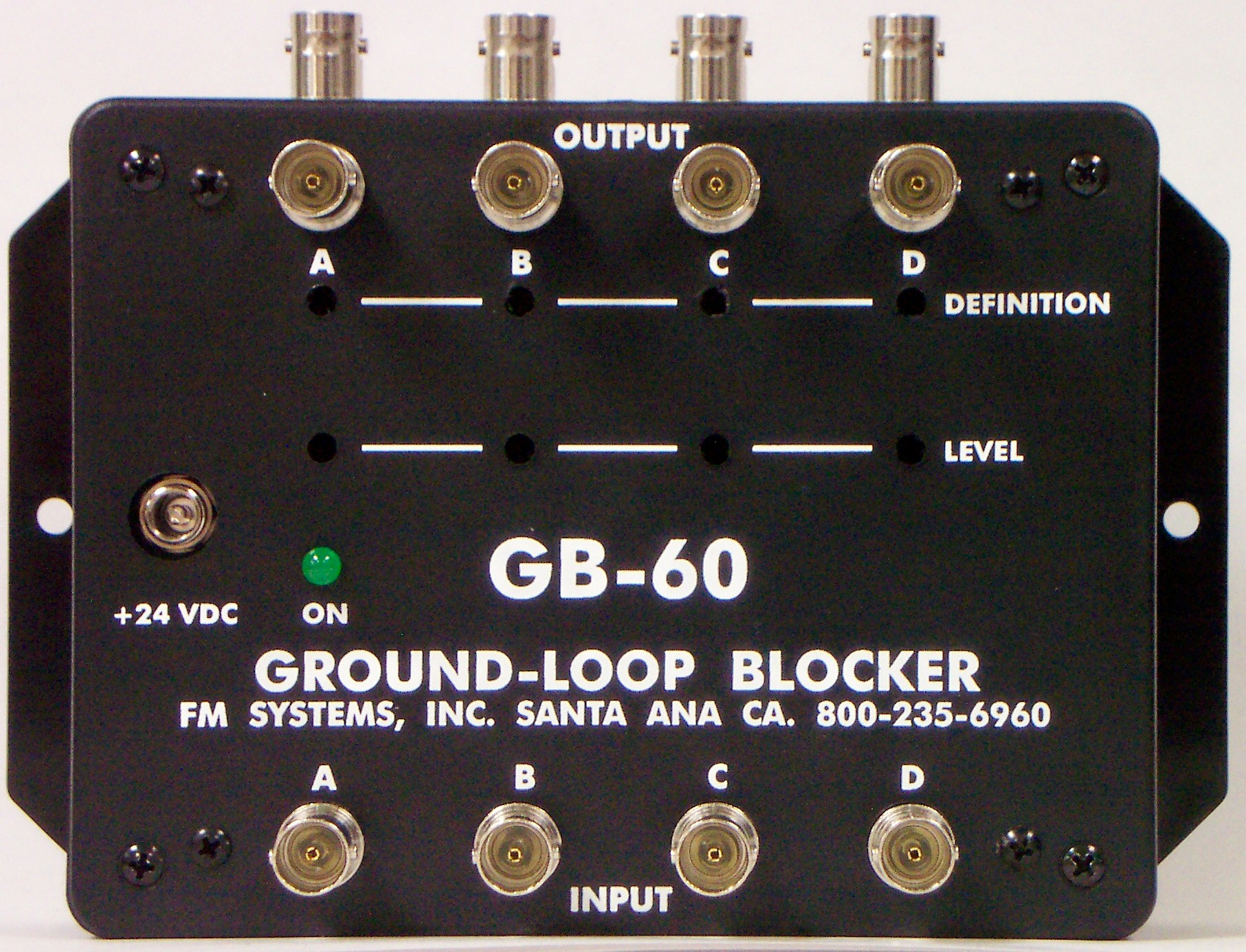
The accepted maximum distance for the UTP transmission is normally about 1000 feet, however this distance can be increased dramatically by the use of cable equalization amplifiers. One such amplifier is the GB60-UTP Ground-loop Blocker that can be used to extend the range or distance of a UTP wire run by equalizing the cable slope loss caused by the cable. The GB-60 is used in the same way to extend the range of coaxial cable runs. Long runs can also exhibit ground-loop interference artifacts which are eliminated by the GB-60 type of amplifier. The GB-60 units are placed at the receiver (DVR) end of the video transmission system. Each GB-60 will correct up to four channels of video.