HOW TO MEASURE SDI CABLE LOSS
HOW TO MEASURE SDI CABLE LOSS
By: Frank McClatchie
One of the major problems facing users of SDI camera signal transmission systems is that the coaxial cable frequently develops greater losses than the Coaxial Cable Manufacturer claims for their product. This excess loss can creep into the cable in many different ways that have nothing to do with the original theoretical loss that the cable should exhibit.
This is a particular problem because of the digital nature of the SDI camera signal. It is the nature of digital signals to work perfectly for various lengths of coaxial cable, until a certain length of cable is reached, and then to fail to transmit the camera signal at any greater loss in the cable. Either the picture is “perfect” or it breaks up or wipes out completely, with no prior warning that “the end is near”.
Thus the major advantage of digitizing a video signal (such as the SDI system), is also the greatest disadvantage to the user of that type of system, in that the user of the system cannot detect excess loss in the transmission system until a slight additional transmission loss results in total failure to transmit the picture at all. This can be a particularly difficult problem when setting up remote or temporary cable runs at sporting events, etc. What is needed is a simple way to measure coaxial cable loss at the highest frequency that is used to transmit the camera signal when that cable is first emplaced to insure that it is capable of carrying the SDI signal. This measurement should include a suitable safety margin of cable loss to insure that changes in temperature, etc. do not kill the signal during use.
These excess losses can be caused by many different field conditions:
1. Excess loss caused by improperly tightened BNC connectors. When BNC connectors are only partially tightened, excess losses can average between a fraction of a dB to more than one dB evenon a connector that “feels solid”, but is not fully tightened.
2. Excess loss caused by incorrect installation of the BNC connector. Be sure to follow the connectors manufacturers instructions very carefully, particularly with regard to trimming the insulation length and the proper shield wire trimming and compression to insure good grounding of the shield to the connector.
3 Excess loss caused by corrosion of the BNC connector. Corrosion can set in to a connector, particularly if the connector is left out in the open, gets rained on, or is slightly loose.
4. Excess loss caused by too many BNC connectors in tandem. Each connector will create additional loss on the cable even if properly tightened. Avoid extra connectors in any given cable run as much as possible. Each connector will increase the total cable loss by a significant fraction of a dB.
5. Excess loss caused by moisture, or even worse, actual rain or sea water entering the connector or a pinhole in the cable. Rain or standing puddles of water will find any pinhole there is in a cable. Try to protect any outside cable from the effects of rain.
6. Excess loss caused by stretching of the cable, even slightly. Pulling a cable should be avoided wherever possible. It is better to un-reel a cable as you go rather than to set up a cable reel at one end and then pulling the cable to get to the other end. The loss of a cable at 750 MHz can actually be increased by the action of stretching the cable.
7. Excess loss caused by short radius bends or “kinks” in the cable. Short radius bends in the cable should be avoided as they will increase the loss of the cable. Actual “kinks” in the cable are capable of producing severe excess loss in the cable that cannot be cured by straightening the cable out.
8. Excess loss caused by cable that has been “run over” thus mashing the cable. Steel wheels are the worst for causing this type of damage, but even inflated tires can cause additional loss in a cable that does not go away.
9. Excess loss caused by cable that has been overheated at some prior time. High temperatures can cause temporary increases in cable loss, but severe overheating can make the additional loss permanent.
10 Excess loss incurred because the cable is still on a spool. The curved cable has greater loss than when it is laid out straight. Tight curves in the cable can cause additional loss. Even the slight loss of a full turn on a reel can increase when the entire cable is on a reel.
Very few of these conditions will incur failure by themselves on short runs of cable, but when the cable is near maximum length, any of these conditions may be sufficient to cause system failure. Often a cable may be plagued by more than one such condition at the same time, increasing the possibility of system failure.It is recommended that reels of cable be tested at regular intervals on any cable that is used for temporary camera installations to reveal any damage that may have been done at some prior time, before the same cable is used for another application.A cable loss record can be attached to the reel so that changes in the cable loss may be recorded and dealt with before the next installation.
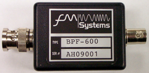
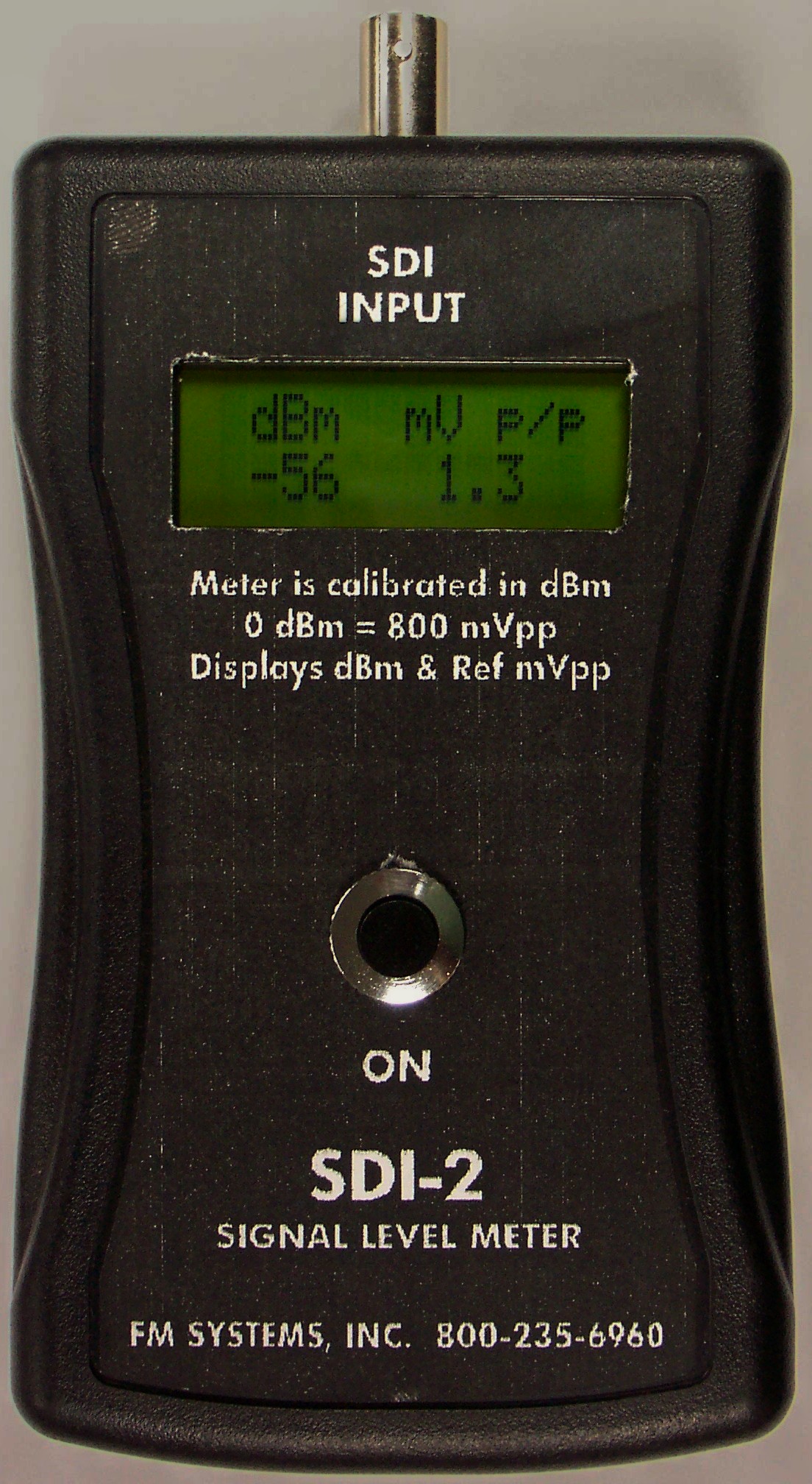
There are two ways that this cable loss measurement can be made. A true power meter, when connected to a high frequency band-pass filter (such as the SDI-2 true power meter, and the BPF-600) can accurately indicate excess losses from any of the above conditions from a given SDI CAMERA and cable combination. If there is no Camera in place to make the test with, the test can still be made by connecting an RF Sinewave Test Generator at the intended Camera location, set to 500 MHz and connected to the cable to be tested, then measuring the received power level with the SDI-2 true power meter. You can get a good look at the high frequency losses of the cable.


