My picture has ghosts and fuzzy edges on it.
Pictures being sent down the cable will reflect back from an un-terminated end of the cable, causing two or more “ghosts” of the original picture to be viewed on the monitor. On very short cables the “ghost” will be almost on top of the original picture and may have the appearance of “ringing” or “edge enhancement”. When the cable is short enough, this edge enhancement may be interpreted as making the picture look “crisper”. In reality any ghosting will result in a loss of picture definition. As the cable length gets greater, the double image effect becomes quite pronounced and is very undesirable.
The key to good clean picture transmission is to insure that each end of every coaxial cable is terminated with the characteristic impedance of that cable.
HOW CCTV TERMINATIONS AFFECT PICTURE QUALITY
By:Frank McClatchie, President, FM SYSTEMS, INC.
Why, where, when, and how to terminate video coaxial cables raises the basic question of what is a termination and why is a termination used in the first place.
First, what is a termination? It is a resistor of a particular value (in video, usually 75 Ohms) that is connected to each end of the transmission cable. In the case of RG59/U type of cable, the resistive value is 75 Ohms. Good terminations use 1% accuracy resistors. Professional Grade terminations are 0.1% accurate.
The Why of termination use is that a picture being sent down the cable will reflect back from an un-terminated end of the cable, causing two or more “ghosts” of the original picture to be viewed on the monitor. On very short cables the “ghost” will be almost on top of the original picture and may have the appearance of “ringing” or “edge enhancement”. When the cable is short enough, this edge enhancement may be interpreted as making the picture look “crisper”. In reality any ghosting will result in a loss of picture definition. As the cable length gets greater, the double image effect becomes quite pronounced and is very undesirable.
When a signal propagates down a cable, it travels at about 70% of the speed of light (.7 times 186,000 miles per second). That means that 500 feet of cable will cause an echo delayed by about 1/4 inch on a 12″ monitor.
Why does any reflection occur at all? The reason lies in the stored energy in the transmission line. Both the inductance and the capacity residing in the cable store this energy. The relationship between the inductance and capacity in a given type of cable determines what the characteristic impedance of that cable is. If there is a resistance at the end of the cable that is equal to the characteristic impedance of that cable, all of the energy will be absorbed by the resistor. If the terminating resistor is either too high or too low, a percentage of the received energy will be reflected back onto the cable to travel back to the source.
For a ghost to be seen at the monitor, any reflected energy from the monitor must first return to the source (camera) and then be reflected back to the monitor. Ghosts make two trips down the length of the cable. If the camera is accurately source-terminated, then the reflection is absorbed there and does not return to the monitor. Cameras that are correctly source-terminated will not cause ghosts, even if the monitor is not correctly terminated.
All Broadcast quality and most CCTV cameras are correctly source terminated with 75 Ohms. However, some low-cost cameras on the market are not correctly source terminated and thus can cause a host of problems. These cameras omit the source termination and thus appear to be almost zero Ohm source impedance. Not only will these cameras cause ghosting reflections, but they will also prevent proper operation of various kinds of interfacing equipment such as Elevation-azimuth (pan and tilt) control and other systems that utilize the Vertical Interval of the video picture for control purposes. The cameras zero Ohm output impedance effectively shorts out these control signals.
There is an easy way to sort out cameras with source terminations from those that are built without source terminations. Connect the camera to be tested to any un-terminated Video Voltmeter or Oscilloscope. Read the Peak-to-Peak voltage and then terminate the metering device with a known good 75 Ohm terminator. Again read the Peak-to-Peak voltage. If the camera is properly source terminated inside of the camera, the voltage will drop to one-half the value when terminated. A non-source terminated camera will reduce in voltage only 1-5 percent when the measuring device is terminated.
Source-termination is not the same as terminating the monitor. Simply placing a termination at the camera will not provide the necessary source termination. The reason for that is that while the monitor termination is placed between the center conductor of the coax and the shield, the source termination must be in series between the output video amplifier (inside the camera) and the output connector.
There are two right and several wrong ways to connect two or more monitors or equipment to a single coaxial cable. The best way is to connect a Video Distribution Amplifier as shown in figure A. The next best way is as shown in figure B.
One prime consideration is that only one termination may be used, it is also important where the termination is placed to avoid reflections and the consequent ringing or ghosting. The correct multiple equipment hook-up requires that the signal from the camera be “looped through” each piece of equipment, and only the last piece of equipment may be terminated as in figure B.
Connecting two pieces of equipment to the same camera with a BNC “T” will work as long as only one piece of equipment is terminated and the coaxial cable connected to the un-terminated monitor equipment is very short (one foot or less). If both cables connecting the BNC “T” to the monitor equipment are long, the coaxial cable coming from the camera to the BNC “T” will “see” a 37.5 Ohm (1/2 of 75 Ohm) termination at the BNC “T”, thus reflecting energy back to the camera. Also the un-terminated cable will reflect energy back to the BNC “T”, causing multiple reflections of various time delays creating a rich source of ghosts and ringing in the picture. Where there will be long cables between monitors, and the loop-through configuration is not practical, a Distribution Amplifier must be used at the junction to enable correct termination of each cable. The key to good clean picture transmission is to insure that each end of every coaxial cable is terminated with the characteristic impedance of that cable.
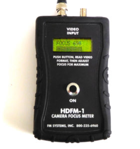
The new HD-TVI and HD-CVI video cameras are more sensitive to miss-termination because they operate at much higher frequencies. If you would like to focus those cameras to the maximum use our HDFM-1 Camera Focus Meter to get the best focus ever.


