

FREQUENCY CONTENT OF HD SDI CAMERA SIGNALS
By: Don McClatchie
Any new technology requires a little effort on the part of the user to learn the basics of that technology to use it effectively. This article discusses the digital HD SDI CCTV camera output signal at the physical layer and the frequency content of HD SDI..
Digital products are generally thought to input and output square wave signals. When I think about anything digital my mind visualizes “On and Off signals” the purest form of square waves, but the world is not so perfect and to transmit a digital signal from one place to another some trade off must be made.
The problem with transmitting square waves is that they occupy gigantic bandwidths, up to ten times wider than the bandwidth required for transmission of the actual information. The highest frequency required to send a series of one’s and zero’s for an HD SDI bit rate of 1.485 Giga-Bits, is 742.5MHz. However wider bandwidths must be used in a transmission system so that the phase shift at 743 MHz is held to a low level to reduce data bit errors. To transmit square waves practically the waveform must be modified to reduce the bandwidth so that unnecessarily high frequencies “harmonics” of lower frequencies do not occur. These harmonics will be phase shifted by the transmission medium and result in a higher bit-error rate that would contribute to system failure.
The output signal from an SDI digital camera is composed of a series of simi-square waves, the actual “Data Transitions” are sinusoidal in the shape of their waveform to reduce the bandwidth. This creates a kind of rounded off square wave that is easily recognizable on an oscilloscope or other data waveform monitor. The SDI signal standard indicates that this transition should occur in no less than 270ps, that’s (270 pico seconds) and no faster. That equals a maximum frequency of 1.852GHz (Gigi-Hertz). This is the highest frequency that must pass through the transmission medium to deliver an SDI camera signal in an unchanged condition, without distortion.
The “Unit Interval” or clock data rate for an HD SDI signal is 1.485 Gb (Gigi-bit), it requires 673.4ps of time to create one bit of data and that is equal to a frequency of 742.5MHz (Mega-Hertz). This is the maximum frequency of the actual information content in the signal. The arrangement of the data itself will create sub harmonics, lower frequencies that are exactly devisable by the Unit Interval or data rate. HD video signals have a word length of 20 bits derived from two parallel 10 bit data streams called Y and C, the Y refers to the luminance sample and the C refers to the two difference Chrominance channels Cb (Chroma Blue) and Cr (Chroma Red). When these signals are combined and serialized they create a repetitive frequency which is called the “Word Clock”, it has a frequency of 37.12MHz. There is a special pathological test signal called the “SDI checkfield” that will exercise the low frequency end of the spectrum to measure for low frequency issues in the SDI video system.
This signal tests the ability of a receiver to “PLL” (Phase Lock Loop) Lock to the incoming SDI video signal.The energy at the Unit Interval and the Word Clock would be much higher than the energy at other frequencies if it were not for the use of a special algorithm that scrambles the data for uniform energy distribution across the band.
Before transmission the raw 20 bit parallel data has been split into two 10 bit parallel data channels. One channel is for the Y portion of the video signal and the other channel is for the Cb and Cr color difference information. These two parallel signals are multiplexed and serialized into one stream sending the data in this order (Cb,Y, Cr, Y, Cb, Y, Cr, and so on. Then this serial signal is converted into an “NRZ” Non Return to Zero signal using an “LFSR” Linear Feedback Shift Register that encodes the data using this mathematical function:
9 4
G1(X) = X + X +1
G2(X) = X+1
Scrambling the signal in this way gives it a statistically low DC content for transmission and the signal will have a greater number of transitions for easier clock recovery in a receiver. The NRZI formatting also allows for polarity inversion without data corruption. Since a “one” is represented by a change in the polarity and a “zero” is represented by no change in polarity, the absolute polarity of the signal no longer has any meaning.
In short, any frequencies above 742.5 MHz are caused by the transitions at the Unit Interval, and any frequency below 742.5 MHz contains the actual picture information you wish to deliver.
The output impedance of an HD CCTV camera is 75 Ohms and it is designed to drive a 75 Ohm cable. Care should be taken to guarantee that only 75 Ohm cable and connectors are used when installing any HD CCTV camera. Beware of exceedingly small diameter cables of unknown origin, it has been my experience that these small diameter cables often do not conform to the 75 Ohm standard. Examine the coax cable shield, if it is actually a braided shield you might be ok. But if the shield is made by wrapping a single wire or multiple wires around the center insulator to create a shield that shield wire also creates a large inductor at high frequencies and will not work for the SDI signal. To be sure you should test any existing coaxial cable you wish to use to determine its frequency response for the SDI signal. The use of video “TEEs” or splitters must be avoided at all cost. Any mis-termination of the cable or connectors can cause “Return Loss” that will degrade the camera signal at the receiver.
By definition, “Return Loss” refers to that portion of a signal that cannot be absorbed by the end of line termination, or cannot cross an impedance change at some point in the transmission system. This portion of the signal is reflected from an impedance discontinuity, and travels back up the line from that point since it cannot be absorbed by the termination or traverse the impedance irregularity. That causes two signals to appear on the coaxial cable, one going in one direction and the other in the reverse direction. These two signals cancel and add along the line at various distances. When these cancellations occur at a receiving terminal end of the cable, data may be lost forever. This is what causes concern with regard to RETURN LOSS on data transmission systems.
“Return Loss” is generated by any change in impedance of a cable (due to changes in physical dimensions, or type of insulation), or for that matter, even coaxial cable connectors used in the cable system, not to mention the actual termination provided by the terminal equipment. In a CCTV installation there can be several sources of these reflections. Most are very small irregularities, but they can add up over many such impedance changes. These irregularities can cause the amplitude and phase (zero crossings) to jitter, and ultimately cause enough error to result in data failure. In addition to the cumulative effect of large numbers of small irregularities, a small number of large discontinuities can also cause this effect. An example of this condition occurs when there is a nearby lightning strike strong enough to burn out or change the value of terminating resistors in the receiving equipment. This can decrease the “Return Loss” enough in that cable section to induce data errors into the system.
In order for a reflected signal to interfere with the original signal, it must first reflect off of the receiving terminal impedance toward the transmitting terminal, then reflect back again from that sending terminal back down the cable and arrive (somewhat delayed) at the receiving terminal. This process creates a long double trip that requires two sets of reflections and the signal loss of two transitions down the cable. This creates some loss in the reflecting signal, but the (direct) signal also suffers some cable loss, so the reflected signal interferes with a weakened direct signal. The greatest possibility for interference occurs when the cable is short and the reflections at each end of the cable are large.
The following table shows the relationship between termination resistance and the return loss value in a 75 Ohm coaxial cable:
75 OHM TERMINATION
TERMINATION LOWER UPPER RETURN SIGNAL
ACCURACY LIMIT LIMIT LOSS REFLECTION
+/- 0.1 % 74.925 75.075 66.0 dB 0.05 %
+/- 1.0 % 74.26 75.75 46.1 dB 0.5 %
+/- 2.0 % 73.53 76.50 40.1 dB 1.0 %
+/- 5.0 % 71.43 78.75 32.3 dB 2.4 %
+/- 10.0 % 68.18 82.50 26.4 dB 4.8 %
+/- 20.0 % 62.50 90.00 20.8 dB 9.1 %
+/- 30.0 % 57.69 97.50 17.7 dB 13.0 %
+/- 40.0 % 53.57 105.00 15.6 dB 16.7 %
+/- 50.0 % 50.00 112.50 14.0 dB 20.0 %
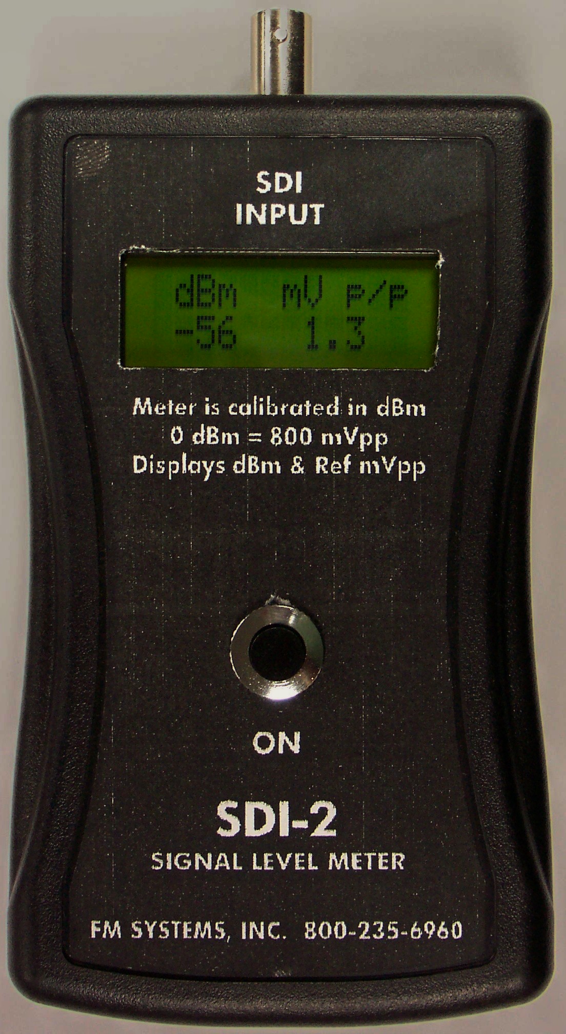
CLICK HERE for more information about the SDI-2
Until recently the main drawback with using an SDI camera was the lack of up-the-coax PTZ camera control. This has recently been solved by using an SDI-D system manufactured by FM SYSTEMS, INC. to add any RS422 PTZ data to the SDI signal carried on the same coaxial cable. It is now possible to add a camera to an HD CCTV camera system that previously used Vertical Interval PTZ Control and still have the PTZ controls. So one coaxial cable can carry the SDI High Definition video signal and also carry the PTZ data signal in the opposite direction on the same cable.
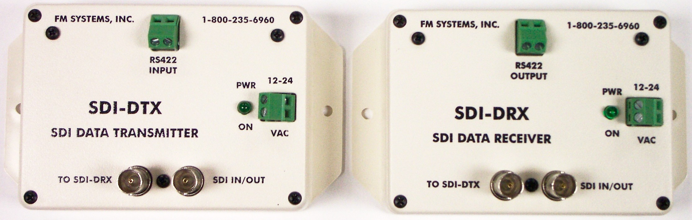
CLICK HERE for more information about SDI-D
In some installations you might want to send contact alarm closures along with the SDI signal up the coax cable or down the coax cable in the opposite direction. This can be accomplished by using the SDI-C system manufactured by FM SYSTEMS, INC. that inserts up to 8 alarm contact closures onto the SDI signal and recovers them at the other end to operate 8 relays. It can be used for gate control, alarm telemetry, or any other contact/relay remote control functions.

CLICK HERE for more information about the SDI-C
When examining all the HD CCTV video camera options always try to get the best performance with the least amount of complexity. You will find the cost of SDI output cameras to be generally less than the cost of IP Cameras because it requires less electronics to generate the signal. Also the installation costs will be lower because you can use the existing coax cable without having to build a network.