DC POWER IS NOT ALL DIRECT CURRENT, THE SNEAKY INTERFERENCE
DC POWER IS NOT ALL DIRECT CURRENT
THE SNEAKY INTERFERENCE
By: Don McClatchie
Just about every CCTV installer has used their Volt-Ohm-milliamp meter to measure a DC power supply voltage for a camera job or a battery voltage for an alarm panel, and most all of them know that you must measure the voltage under load, that is the camera or battery load must be attached when you take the measurement to get a correct reading.
However, many installers overlook one measurement that can be very useful especially when trouble shooting unknown problems. As power supply connections go, there are basically two types of current to run cameras and equipment, DC (Direct Current) and AC (Alternating Current). Your camera will use one of these two types of current to operate. If your camera uses AC then the measurement is simple and you use the AC input on your meter to get an accurate reading of the voltage and that is it.
If your power supply for the camera is DC then you should be measuring two different types of voltages. The first and obvious one is to measure the supplied DC voltage and this you do by using the DC input on your meter as you have always done. Now to make a complete assessment of the power supply you should also measure the amount of AC or “ripple voltage” that you have on the supply. All DC power supplies have a small amount of AC ripple Voltage on them and the problems start when the AC ripple voltage is too high. Of course, all of the AC and DC voltage measurements must be made with the load attached for accurate results particularly the AC ripple measurements because they are very sensitive to load variations. Since both DC and AC can exist on your power supply line it is prudent to measure both voltages and be aware of the AC ripple level and to know how much is too much AC ripple.
So, what happens if my DC power supply has too much AC on it? Well one thing that can happen on a video camera is the appearance of black horizontal bars that you would think are ground loop bars, in fact they look just like ground loop bars but do not originate due to double grounding as is the case with ground loop issues. Or it can cause many tiny vertical lines that dance around very energetically and roll through the screen. Also, a camera can go on and off in a rhythemic way every few seconds as a result of this type of interference.
To understand how the interference gets into the video you need to know just a little bit about power supplies and how they are made. Basically, there are two types of DC power supplies, analog and switching types. You will know the analog type because it will be heavy in your hand due to the large iron transformer used to reduce the primary “mains” voltage down from 120 VAC to the secondary low voltage side. The switcher type of power supply will be very light in your hand as they typically convert the mains down to a low voltage by switching the current on and off very quickly reducing the duty cycle to achieve a lower voltage.
The low priced analog types are usually load regulated (not really regulated) so that when it is unloaded it will measure a voltage some 20% above the stated or working loaded voltage. These types of power supplies step the line voltage down from 120 AC to the low voltage side with an iron transformer and then use a bridge rectifier to turn the AC into PDC (pulsating Direct Current) and then they have capacitors to smooth out the DC and remove most of the AC ripple. It is important to note that as these types of power supplies age the ripple AC will steadily increase until you could begin to see what looks like ground loop bars in the video image, it normally takes years for this to happen. The interference is not a ground loop but it is a power supply interference entering into the camera and getting though the cameras power supply filters and then onto the video by way of the amplifiers inside the camera creating the source video.
Now a switching power supply is built much differently and they display a much different problem when they age. Inside the typical switching power supply the line voltage is used to create an oscillation working from Kilo-Hertz (kHz) to many Mega-Hertz (mHz) in frequency. This frequency exorcises a much smaller step down transformer with a secondary output that is then rectified and filtered to remove most of the AC ripple and then some of the voltage information is feed back to the oscillator to control the output DC voltage. These types of power supplies are regulated by the feedback and will measure the correct working voltage regardless of load right up to their current limit.
Now this type of power supply creates a very different kind of interference when the components begin to age. When the capacitors age their ability to filter out the high frequency oscillator begins to weaken and the result is you will see many hundreds of vertical or horizontal lines on the screen and they will move about furiously. This is because the AC kHz to mHz oscillator signals are now entering the camera and going straight though the cameras power supply into the video amplifiers and out onto the video. Camera power supplies are not designed to remove high frequency AC on the DC power input.
So how much AC ripple is OK? As a rule of thumb, no more than 5% of the loaded voltage should be allowed. When you measure a new power supply you should measure a much lower level of AC ripple, but for older power supplies with weak filter capacitors you can use the 5% level as a good starting point. If the power supply is over loaded the ripple will go up fast as the filter capacitors were not designed to handle that level of current spikes. So, take a look and measure a few power supplies to get a handle on what works so you will know when a power supply is causing trouble or could cause trouble in the near future.
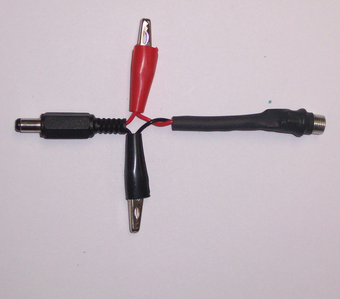
Some systems come with pre-terminated power connectors that make it difficult or nearly imposable to get your meter on the conductors to make AC and DC measurements under load (with the equipment attached). One trick is to use sharp probes on your voltmeter and stick the insulation of twin lead power wires and if it is done carefully you can get your reading and the insulation will swell back to seal the tiny hole made by the meter probe. However, if the power wire takes on the form of a coaxial type construction with an inner core wire surrounded by a shield conductor, that method just won’t work. When this type of power wire is used, it is useful to arrange ahead of time, a small tool to give you access to the loaded power supply.
POWER ADAPTOR
To measure the power wires while they are plugged into the camera and operating you need to make up a connector using both the male and female type of power connector used on your type of camera and arrange for a set of alligator clips or meter probe points to be wired to the connectors so that you can put it into the path of the power, power up the camera and still connect your voltmeter to the power at the camera or supply end.
When you have measured a few, and looked at some aged power supply readings you will have a good handle on what is good and what is questionable and knowledge will serve you well. Also, if you seem to have a ground loop type of interference on the video screen that shows up even on a battery powered monitor look to the power supply source for the answer.


