

COMMON MODE SUPPRESSION IN THE IP VIDEO SYSTEM
COMMON MODE SUPPRESSION IN THE IP VIDEO SYSTEM
One of the most obvious differences between IP video installations and all other forms of video transmission is the cabling used to communicate between the camera and the NVR Network Video Recorder. This cabling uses multiple pairs of twisted wire in the same jacket and crimp on connectors called 8P8C the slang term is RJ45 connectors. It is referred to as a balanced transmission system employing common mode suppression because it uses two equal but opposite polarity signals on any one wire pair and has no ground associated with the network cable. Also IP video signals require two way communication on two separate wire pairs to deliver a video signal.
Unlike coaxial cable the network cable has no external shield covering the transmission wires to prevent outside interfering signals from getting onto the wires and mixing with the signal, this is done to reduce high frequency signal loss that a ground shield would induce and with out it significantly reduces the cost of the cable. Instead of shielding the network cable as it is with coaxial cable, the network cables uses a different method to reduce the level of outside signals from getting onto the wires and interfering with the IP video signal.
All network cables are manufactured with twists in the individual wire pairs, this is vital to the proper operation of the IP system. It may not be noticeable to the naked eye but each of the pairs of wires have a different amount of twist per foot, this is also extremely important to the IP system transmission. The twists alone do not prevent interfering signals from getting onto the wire pairs and in fact any interfering signal that is nearby has an unshielded direct path right onto the wires. However the fact that the wires are twisted will allow the system to remove the interference later on, also the differences in the twists help prevent cross talk between the wire pairs. Interfering signals and crosstalk are the two main factors that limit the maximum distance any network cable can be run and so suppressing these interfering signals is vital for a successful IP installation.
So what is Common Mode Suppression and why is it important? In a balance system each wire pair has an equal and opposite polarity on it at any one time. So at the receiver end of the transmission we can say with great certainty that any signal that is the same polarity on each of the two wires at the same time is an interfering signal and can be removed. Amplifiers at the input of the IP receivers are designed to remove any part of the signal that is the same in phase and amplitude between the two wires instantaneously.
The removal of all signals that are common to both wires is where the term Common Mode comes from and it works very well as it relates to outside interfering signals. However any part of the original wanted signal that is converted to a common mode signal in the wire run will also be removed and that is seen as a loss of the intended signal.
So how does the intended signal get converted to a Common Mode signal in the wire run and how can it be prevented? Let’s look at the different ways Common Mode signals are created from the intended signal. The primary culprit in Common Mode conversion is within the network cable itself. Poorly manufactured cables will create common mode signals all by themselves and cable can be damaged when installed and create the same effect. The actual reasons for this are mechanical non-uniformities in the manufacture and handling of the cable.
Starting with the single wire itself a non-coaxial application of the insulation that is not the same thickness all around the wire will cause unequal capacity to surrounding wires and its own wire pair. This capacity change will cause high frequency losses to be different between the two wires in a pair and this will allow external sources of interference to enter the two wires with different levels and so the signal will not be removed in the receiver. For a “perfect” exclusion of outside interfering signals using common mode suppression, the wire cable construction and twists would have to be theoretically perfect. To the degree they are not, the outside interfering signals will get in. The better the cable construction is the less interference you have.
In the manufacturing process the wire is drawn down to size the diameter of the wire gage. If the wire is not the same size both the inductance and the capacity of the insulated wire will vary and this in turn will cause a percentage of interfering signal to become differential and it will be received as interference.
To the degree the twists in the wires are not uniform over the length of the cable cross talk between the wires will cause interference in the signal. If your network cable uses a separator non uniformity of the separator between wire pairs will cause a small degree of interference in the transmitted signal and so a reduction in the distance you can use with that cable.
Cost is not always an indicator of good quality network cable. Using a higher grade or Category of cable is usually a good way to get longer runs that will work well. But in the end trial and error is the only true test of any cable. Try to use the same manufacturer when ever you can and that will reduce your installation variation. Damage to the cable like stretched cables or too sharp a bend radius or cable that has been flattened by being smashed or stepped on and particularly wet cables can also cause un-balance and induce common mode even with a good manufactured cable.
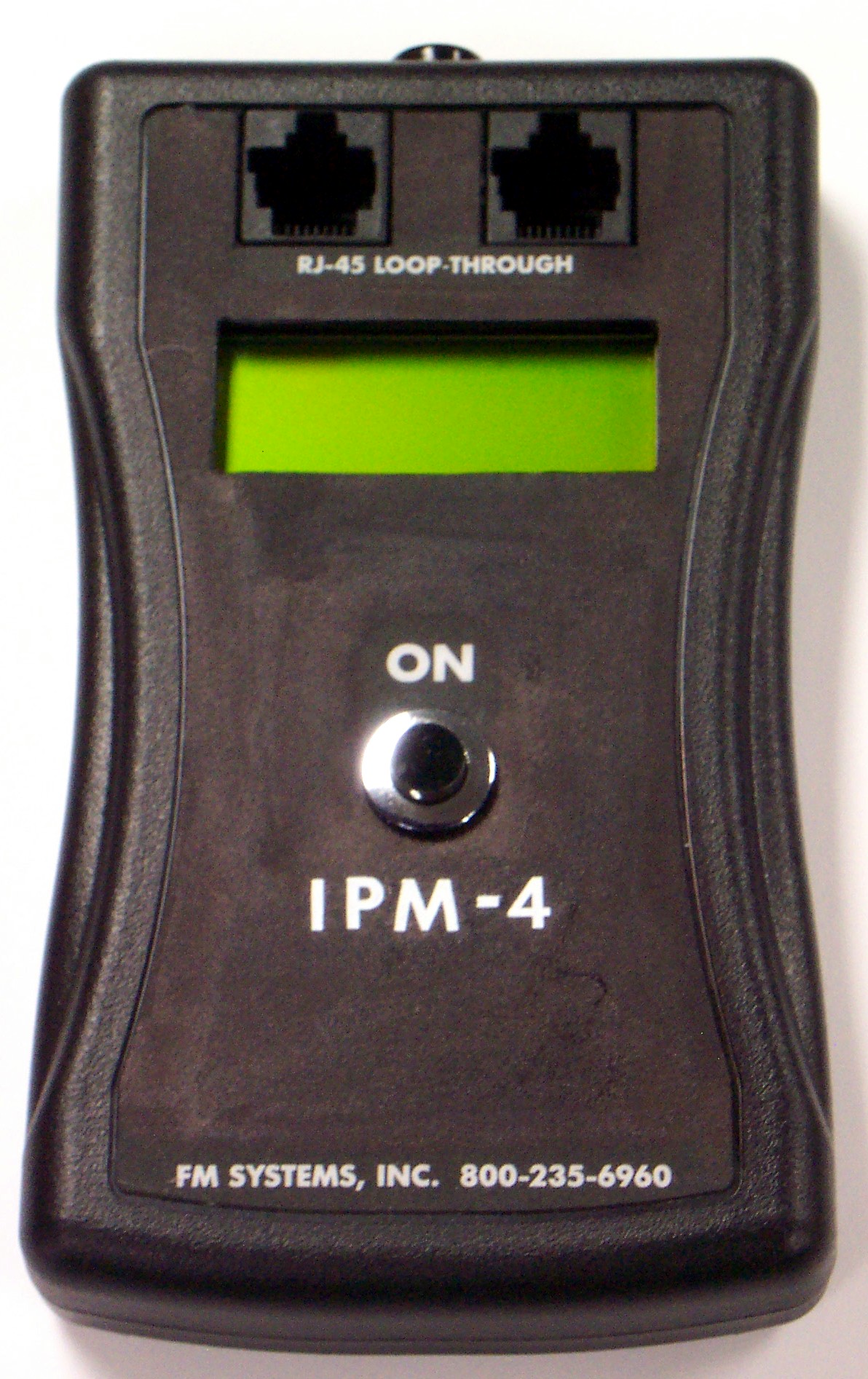
So besides the maximum cable length limitation how would the technician know which cable is better than any other cable or for that matter whether any system is near the digital cliff (fail point)? The easy way is the measure the signal level, balance and common mode for confidence. The meter must be able to measure these three things to give the installer the assurance that the signal meets the minimum operating specifications for prolonged operation in any environment. There is a meter that will make these tests called the IPM-4.
The IPM-4 digital video level master is used to measure the signal quality of an IP video network. This low cost meter makes 6 different level measurements to give you assurance that your IP video system is working within specifications. It measures the output levels of both the camera and the recorder end of the system in dBm so you can check the near-end and far-end signal levels and cable loss simultaneously. The meters unique design also measures the percentage of signal imbalance in that exists on both the sending and receiving channels which contributes to cross-talk and increases the bit error rate in your digital video. Then it measures Common Mode signals in dB, a form of interference caused by phase and amplitude variations that also causes video failure. With an IPM-4 you can install you IP video systems with confidence.
IPM-4
IP VIDEO MASTER
FOR MORE INFOMATION CLICK HERE