CCTV VIDEO, WHATS IN YOUR TOOLBOX?
CCTV VIDEO, WHATS IN YOUR TOOLBOX?
By: Don McClatchie
FM SYSTEMS, INC.
All CCTV installers have a basic set of tools they have accumulated over time to help them do their job quicker and easier. Often a $1.00 item on hand in your toolbox can save you dozens of hours of work and thousands of dollars over time. This article will discuss some of these low cost items and how to use them, so whats in your toolbox?.
Here is a short list of the tools you should have in your toolbox besides screwdrivers, pliers and other hand tools.
V.O.M. Meter
75 Ohm BNC Termination.
BNC “Tee” Connector.
Power Adaptor Cheater Plugs 2 pieces.
50 foot extension cord.
#5 Welders Glass.
Alligator Jumper clips.
Video Baluns.
THE V.O.M. METER:
I think it is safe to say that the VOM “Volt Ohm Meter” is by far the most widely used tool when installing cameras and other CCTV equipment. This meter is very often under utilized during the installation process. Here are some techniques you can use with your trusty VOM, some you will know and some you may not.
MEASURING VOLTAGE:
Use the VOM in the voltage mode to measure the power supply for the camera (at the camera). The reason you must measure the voltage at the camera is that the series resistance of the supply wire will cause a drop in the delivered voltage when current is flowing. To get an accurate voltage reading you must measure the voltage with the camera equipment connected under normal load. Remember that if the camera has LED illumination, heaters, or any other equipment using the same wires you must measure the voltage with all loads on at the same time to assure proper systems operation.
MEASURING RESISTANCE:
The resistance measuring function of your meter can be used to measure continuity to test for opens and shorts on wires and it can also be used to measure video termination resistance and cable distance. If you attach your Ohm meter to the input of any video equipment such as a monitor or DVR with one probe on the BNC shield and the other probe at the center conductor you can determine if that equipment has the correct 75 Ohm internal termination.
The internal 75 Ohm termination can be damaged by lightning and transient voltage spikes or they may just be switched off. In each case the resistance measured will be higher than 75 Ohms. A wrong termination resistance will cause ghosting or a signal that is too high in level. Some DVRs will fail to display a signal if the level of video is too high and say no video or have a blue screen.You can even measure a cable length with your VOM using the resistance measurement.
All cable has a DC resistance in fractional Ohms per foot. If you short circuit the cable at one end and measure the total loop resistance of the cable at the other you can determine how long the cable is with reasonable accuracy. Take the cable that you use and measure a 10 foot piece shorted at the end. Write that number down and keep it, then when you need to know where a cable goes knowing the length will help you track down where it goes. You may even discover another piece of equipment in the system that you didn’t know was there. If you get an Ohm meter reading 75 Ohms greater than you expect you probably have a piece of video equipment in series on your cable.
THE 75 OHM BNC TERMINATION:
A 75 Ohm BNC termination is a BNC male connector with a 75 Ohm resistor inside the connector. It is used to terminate video when no internal terminations exist in equipment. Most all CCTV equipment has the required 75 Ohm termination built in, but in some cases this termination may not be there.
It is easy for a termination to become damaged by lightning or a transient voltage on the video cable. This results in the 75 Ohm resistance being fused out completely or having its resistance raised above 75 Ohms. This in turn will cause a higher than normal video signal at the receive end of the system. It will also cause ghosting in the picture as a result of reflected energy not absorbed by the damaged termination. When you think you have a good video signal but your DVR will not display a picture measure the termination resistance at the input to the DVR or monitor.
Another use for the 75 Ohm termination is to use it as a temporary signal attenuator for troubleshooting. Some DVRs are sensitive to high level signals coming from hot cameras. When the video signal is too high the DVR will display no picture or a blue screen. When you suspect that the video signal is too high for the DVR insert the 75 Ohm termination onto the cable just ahead of the DVR.
Use the BNC “Tee” connected to the termination to get it onto the video line. This connection double terminates the video and lowers the signal level below the suspected overload level. If the picture returns to the DVR (it will be darker than normal and may have ghosting) then you will know that the level reaching the DVR is too high and must be reduced in level. Use the Iris adjustment on the camera to reduce the video level.
POWER ADAPTOR CHEATER PLUGS:
Ground Loop problems can be found in many CCTV installations. When you have a ground loop you will see black horizontal lines at least two on the monitor or a tearing of the picture at the top of the monitor screen. To find the source of the ground loop interference you must be able in isolate the grounds on one or more pieces of equipment. This is where the Cheater Plug becomes useful. A power plug Cheater Adaptor plug has a normal grounded three prong female plug on one end and a two prong non-grounded male plug on the other end. It may also have a green wire coming out of it that is not used.
In all CCTV installations the DVR should be grounded to the power ground. However no other equipment should be grounded except through the coax cable shield back to the DVR. The problem comes when the camera or other equipment is grounded to a different ground in the electrical system. Current from one ground will try to flow to the other ground through your coaxial cable. This is what creates the ground loop problem. To find the source of the ground loop you can lift the ground temporarily by powering equipment through the Cheater Plugs to determine where the ground loop is getting into your system. Have a couple of them on hand to make these tests. When you locate the extra grounds you can remove them from the system.
50 FOOT EXTENTION CORD:
Have you ever had interference in your CCTV monitor that exhibited dozens of narrow vertical lines either black or white, and as thin as a pencil line. They may be staggered or jagged from the top of the screen to the bottom and may even dance side to side slightly while standing in one place or move across the screen slowly from side to side.
If the lines stand still and dance around one spot your cameras are line locked, but if they slowly move across the screen then your cameras are not line locked. If you have this kind of interference on your monitor, there is a good chance that the system is being powered by a UPS and that the interference is coming directly from the UPS.
Some models of UPS Un-interruptible Power Supplies will induce interference into your CCTV picture. This interference can enter your CCTV system through the ground in the case of shared grounds like a ground loop or directly through the power supply used to power the camera. Technically UPS power supplies come in two output types. The most common kind is the low cost square-wave output type, like the kind used for computers and sold in computer stores, the second less common kind is the sine-wave, simi-sine-wave or quasi-sine-wave type used to power analog equipment.
The word “sine-wave” refers to the output waveform being sinusoidal in the shape. A pure sine-wave has only one frequency, and in the case of line voltage that frequency is 60Hertz or (60 cycles per second). The output of this type is well filtered to remove all other frequencies that might interfere with the equipment it is powering.
The “square-wave” type of UPS will put out the same 60Hertz frequency but its output waveform is that of a square-wave. A 60Hertz square-wave signal contains the “fundamental” or lowest frequency of 60Hertz, however it also has every “harmonic” or multiple of that frequency all the way up to and beyond the video frequency range. Strong high level signals in the Kilo-Hertz region (1000Hz) and even in the Mega-Hertz region (1000,000Hertz) will interfere directly with video. These interfering signals are multiples of 60 Hertz and are locked to the line rate which makes the interference stand still on the screen if your cameras are line locked. If not line locked the interference will slowly move across the screen.
One way that the interfering signal can get into the CCTV system is from a power supply. If a square-wave type UPS is used to power the camera, the high frequency interfering signals can enter through the AC or DC power supply and become part of the video by cross-talking directly to the video amplifiers in the camera. The high frequency interference will get through the cameras power regulators because the camera was designed to filter out 60Hz AC, not hundreds of Kilohertz of AC. DC powered camera’s can have the same problem for the same reason, however the interfering signal will always be moving on the screen because DC cameras cannot be line locked.
Another way interfering signals can enter the video is through an induced ground loop. The UPS is grounded and if the camera is also grounded some of the UPS energy can flow down the coax cable to the cameras ground. This sharing of grounds will induce the interfering signal onto the video. A ground at the camera can be a tricky thing. If you are using a DC powered camera, the coax cable shield and the negative power supply wire are the same at the camera. This means that if the negative power supply is grounded anywhere, then your camera coax shield is also grounded at that point and it can induce a ground loop.
If you are using a common power supply to power multiple cameras and even one camera is grounded then the ground connection will back up to all of the cameras. Common power supplies for DC cameras are especially susceptible to this problem. The common power supply ground loop may not affect all the cameras depending on the distance of coax and the grounding conditions at each camera.
To begin trouble shooting you must first identify the source of the interference. First disconnect the suspected UPS and turn it off (power it down). This will guarantee that the UPS cannot create the interference in the first place. Use the 50 foot extension cord to reconnect the equipment that was powered by the UPS to a normal non UPS power Source. Check the monitor and see if the interference has been eliminated. This test will check for direct camera power supply and ground loop type interference at the same time.
If your interference did not go away and you suspect that another UPS somewhere else in the building is operating, you can check for ground loop interference by placing a battery operated monitor on the end of the coax cable at the DVR end of the system. Observe the monitor. If the interference is gone, that indicates ground loop interference.
Confirm this by touching the original DVR ground to the connector shield on your battery operated monitor while you are watching the picture. Use a short wire or a coax jumper (shield only). If you touch the ground to the monitor the interfering signal will re-appear if it is ground loop induced interference.
If the interference is resolved by disconnecting the UPS then you should replace the UPS with a sine-wave, simi-sine-wave or quasi-sine-wave type of UPS. The best way is not to create the interfering signal in the first place. If the interfering signal is getting in through a ground loop then isolate the cameras from ground at the camera end. This may be more difficult when using common power supplies however first try an isolated wall mount power supply on one camera to test whether power supply isolation will resolve the problem.
#5 WELDERS GLASS:
Have you ever wondered why Auto Iris cameras seem to go out of focus at night? Many installers have had to return to the job site at night and reset the focus of a camera to solve this problem.
All lenses have a characteristic called Depth of Field. Depth of Field is a zone in front of the lens that is in focus. It is measured as the minimum distance and maximum distance from the lens where objects are in focus. All objects inside this minimum and maximum bracket zone will be in focus. The further away you go from this bracketed “in focus zone”, either toward or away from the camera the more out of focus the objects become.
The Auto Iris lens has a movable aperture inside the lens that controls the amount of light allowed to pass through it. This aperture also directly controls the Depth of Field of the lens. So an Auto Iris lens will have a variable Depth of Field depending on the amount of light entering the lens. This causes the minimum and maximum bracket zone of focus to change when the lighting level changes.
During the day or in bright lighting conditions the Iris is closed down to a small opening, and the Depth of Field is quite large. So called Pin Hole cameras exhibit this effect where all objects in the scene are in focus. However with movable iris cameras at night or in low lighting conditions the Iris is open wide, this causes the Depth of Field to collapse down to a smaller minimum and maximum bracketed zone of focus. An object that was inside the zone of focus during the day can be outside the zone of focus at night
One way to set up the camera to minimize the Depth of Field problem, is to adjust cameras focus at a time when the light level is at its lowest. This may not be convenient for your installers.
The best way is to use a SHADE 5 FILTER PLATE also called a #5 welders glass filter. It is the filter plate that welders look through to protect their eyes during welding operations. When you have full daylight or bright lighting conditions the filter plate is placed over the cameras lens to simulate half lighting conditions.
This filter plate costs only a few dollars and should be carried by installation personnel to every job site for use with Auto Iris lenses, especially those jobs using outdoor cameras. By using the filter plate to adjust the Auto Iris, you will be centering the control range of the Auto Iris system. This will give you optimum performance from your cameras Iris control system.
Hand held focus meters such as the CM-2 Camera Master are also useful in determining the maximum focus of any scene. They are more accurate than large screen monitors and much easier to take up a ladder. They display the maximum focus numerically on an LCD type display. By eliminating the subjective nature of focus setting, you will insure that all cameras will be set to their maximum focus by any installer.
ALLIGATOR JUMPER CLIPS:
These quick connect clips are useful for connecting your V.O.M. to make a measurement when you are working one handed on a ladder or when you need to short circuit something to make a test. Sometimes you will want to temporarily connect a ground to a piece of equipment or connect the grounds of two pieces of equipment together and a sturdy alligator jumper works well. It can be used to short circuit the end of a BNC cable for the resistance distance measurements.
VIDEO BALUNS:
If you work with UTP Unshielded Twisted Pair wire video installations or you might have to troubleshoot one, you will need to have at least two video baluns in your tool box. You can use them to temporarily replace a suspected bad unit and can be used to bypass active sending and receiving units that may be putting out too much level or not functioning at all. Too much level will cause a condition called “DVR overload” that prevents the DVR from recording the video signal.
A HELPING HAND:
Perhaps the most powerful tool you can have in your toolbox is this telephone number, keep it close. If you cannot isolate the problem or resolve the interference then please contact me at: 800-235-6960 my name is Don McClatchie and I would like to talk to you about your specific problem. “Two heads are better than one”, together we can find the solution to your problem.
ONE MORE TOOL:
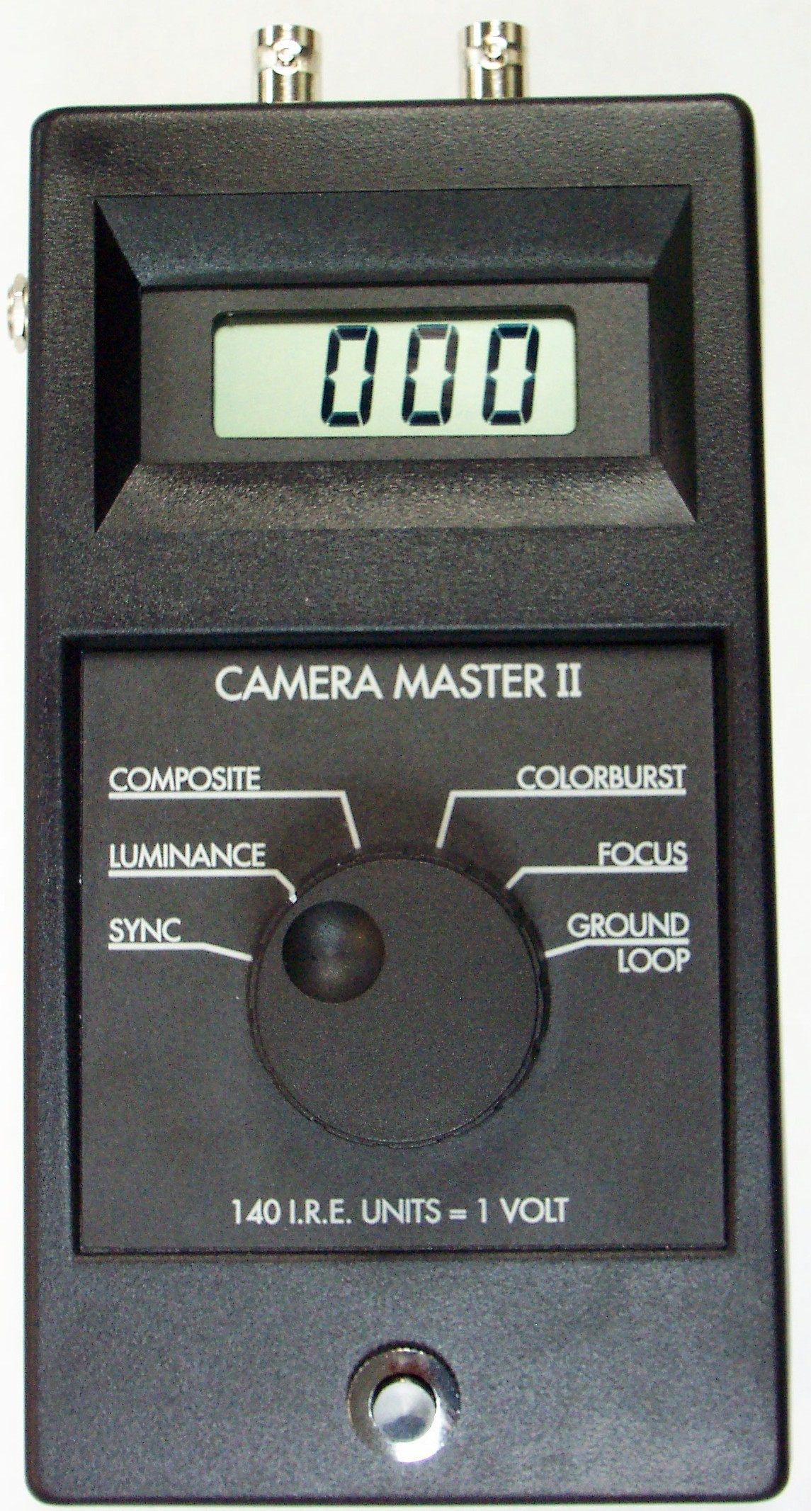
The Camera Master CM-2 is a digital, hand-held, battery operated meter that measures six different characteristics of any video signal. Use it for fast and accurate set-up of any video source.
SYNC (40 IRE Units) Use this to check for correct end of line terminations and camera sync output level.
LUMINANCE (100 IRE Units) Enables the camera Iris to be accurately adjusted to the correct brightness setting for uniform level and to prevent DVR overload.
COMPOSITE (140 IRE Units) Measures the peak to peak level of the video signal. 140 IRE Units = One Volt of video.
COLOR BURST (40 IRE Units) Measures color burst amplitude on the Back Porch of video. Used to measure cable slope loss at high frequency and adjust video amplifiers.
FOCUS Used to adjust camera for best focus on scene. Maximum meter reading occurs at sharpest focus. The digital read-out eliminates subjective guess work.
GROUND-LOOP This measures the troublesome 60Hz ground loop voltage that causes Bars on the video picture. You can use this measurement to verify that no ground loop exists in the video before you leave the job.
The Sync, White, and Composite amplitude measures the sync-to-white ratio and the overall video waveform amplitude on any part of an NTSC CCIR (CCTV) or PAL video system, including camera origination, video levels in Distribution Amplifiers, Video Switchers, CCTV installations, Studios, Microwave and Satellite transmission systems. The hand-held battery operated CAMERA MASTER will allow you to take video measurements anywhere. You will be able to trouble-shoot camera installations and do the job faster with confidence.