CABLE SLOPE LOSS CAUSE AND EFFECT
CABLE SLOPE LOSS CAUSE AND EFFECT
By: Don McClatchie
Cable Slope Loss is the main cause of most long run video image quality issues. Whenever video is sent down a long coaxial cable, or an Unshielded Twisted Pair (UTP) cable the video will arrive at the other end of the cable with a lower quality picture. The amount of picture quality loss you get is directly related to the length of the cable and the cable classification or type of cable. Some installers will use a better classification of cable on long runs to reduce the picture detail loss, but what’s different about that kind of cable besides the higher cost per foot?
All coaxial cables and UTP cables used for video are composed of oxygen free copper wire conductors and an insulator material to separate the conductors. The physical size of the copper conductors and the size and material type of the insulators determine the loss of coaxial cable and UTP cable.
Every conductor has resistive losses measured in fractions of an “Ohm” per foot which is determined by the cross section or diameter of the wire. This resistive loss attenuates or reduces the video signal the same amount at all frequencies. This is referred to as “flat loss”.
Any length of copper wire also has the property of “Inductance”, which makes it act like a coil with “Inductive Reactance” that affects AC signals like your video signal. This inductive reactance will result in non-uniform losses at different video frequencies.
Last, but not least the insulator material used in the cable when applied to the copper has a “Capacitance” effect measured in “Pico Farads” per foot. The capacitance will introduce non-uniform losses at different frequencies also.
Every cable and UTP wire has resistive, inductive, and capacitive effects distributed evenly along the cable that result in a very predictable “Roll Off” of the high frequencies, or more loss at high frequencies than at the low frequencies. Generally the higher the frequency, the greater the loss due to the resistance, inductance and capacity of the cable per given length of cable. This is referred to as ‘High Frequency Roll Off’ where the cable effectively creates a Low Pass Filter because of its physical properties. This effect is well known and there are tables that indicate the loss at various frequencies and cable lengths of different types of cables.
Since we know the loss of each type of cable per unit length, it is possible to build a circuit call a “Cable Equalizer” with exactly the reverse of that loss, and thus when a long cable and an equalizer are connected with each other, the cable loss can be completely eliminated.
Cable Slope Loss effectively reduces the bandwidth or high frequency content of the video signal which reduces the picture sharpness, but why does the picture sharpness diminish with reduced video bandwidth?
Video cameras have a CCD (Charge Coupled Device) just after the lens for converting the light energy of the image into electrical impulses that are output as the video signal. The CCD is rated by the number of pixels it has etched onto the face of the device. The number of pixels refers to the number of individual light gathering elements stretching across the chip horizontally. All standard analog video cameras have 525 lines from top to bottom that constitutes the vertical line standard. However the horizontal line count has many standards from about 380 lines (low resolution) to over 800 lines (high resolution), these lines are referred to as “Lines of Resolution”. The greater the lines of resolution, the sharper the picture can be.
If you were to alternate black and white pixels across the monitor screen you would see vertical lines representing each displayed line as a black or white vertical line. As the bandwidth is reduced by cable slope loss the division between the black and white lines becomes blurred into varying shades of gray. This is what is happening when long cables reduce the sharpness of the video image. The sharp edges of the detail in the picture are blurred into gray reducing the sharpness of the image. There is a direct relationship between lines of resolution and bandwidth.
Since some equipment quality is rated in Bandwidth, while other equipment is rated in Pixels, it is useful to know how the two measurements relate to each other. To discover the Pixel equivalent of a certain bandwidth, simply multiply the bandwidth in Mega-Hertz by 106.7 to discover what the equivalent Pixel count would be. To calculate the equivalent Band-Width in Mega-Hertz for a given Pixel Count divide the Pixel Count by 106.7. In this way you can convert Pixel Count to Bandwidth and the reverse.
Your cables Characteristic Impedance can cause unusual losses in video applications also. One of the main specifications used to describe a cable is referred to as Characteristic Impedance of the cable. There are three major categories of characteristic impedance for coaxial cables, 50 Ohm, 75 Ohm, and 93 Ohm cable. How is the characteristic impedance determined? What exactly must be measured to determine this impedance? Aside from looking up the number of the cable in the manufacturer’s specifications, there does not seem to be any obvious physical characteristic about the cable that clearly indicates just which impedance a given coaxial cable has.
One way to test for this impedance is to apply a high frequency signal to the cable and measure the current that flows into the cable. This is a highly technical process and fraught with numerous sources of error.
Another way is to measure the capacity per unit length and the inductance per unit length, divide the capacity into the inductance and compute the square root of that number. The result is the characteristic impedance! As a practical matter, most people simply take the number attached by the manufacturer and look up the impedance. As always you must use the proper terminations at each end of any cable, and they must match the cable.
Failure to terminate a cable with its own characteristic impedance at both ends of the cable is really asking for trouble. Failure to match the characteristic impedance of the cable with the equipment impedance will result in that part of the signal energy that is not absorbed at that termination, reflecting back to the other end of the cable, resulting in multiple images (ghosting) in the picture. Usually a failure to properly match one termination does not necessarily create multiple images because a second reflection will not occur unless the other end of the cable is also miss-terminated.
Some Camera manufacturers take advantage of this condition by designing in a “zero Ohm” source impedance with a one volt video signal, instead of the two volt signal required with a proper 75 Ohm source impedance. That is definitely not a good idea because it is almost certain to result in “edging” or “ringing” at picture edges or multiple images referred to as ghosting if the receiving termination does not perfectly match the cable characteristic impedance.
Lighting can “cook” a termination at either end of the system thus changing the termination resistance even very slightly. Having a good cable termination at both ends of the cable is good insurance against future ringing and ghosting picture problems.
In the case of RG59/U Coaxial cable that means that the sending end (source) Termination must be 75 Ohms and the receiving end termination must also be 75 Ohms. In the case of UTP cable, the sending and receiving end terminations must be 100 Ohms. Any energy traveling down the video line must encounter the characteristic impedance of the cable at the end of the cable, or the portion of the energy that was not absorbed, will bounce back onto the cable and return to the original source, in affect creating an “echo” of the original signal.
Depending on the length of the cable “ringing” can be observed at the edge of the signal or if the cable is long enough multiple echoes of the original signal will be observed. When this condition is discovered it is only necessary to replace the termination with the correct value. When the source termination in the camera is damaged it is usually necessary to replace the camera itself because the termination is entirely internal to the camera and cannot be repaired. Lightning strikes are a common cause for this type of problem. The resistance of the internal source impedance may have been altered by a brief surge without destroying the camera.
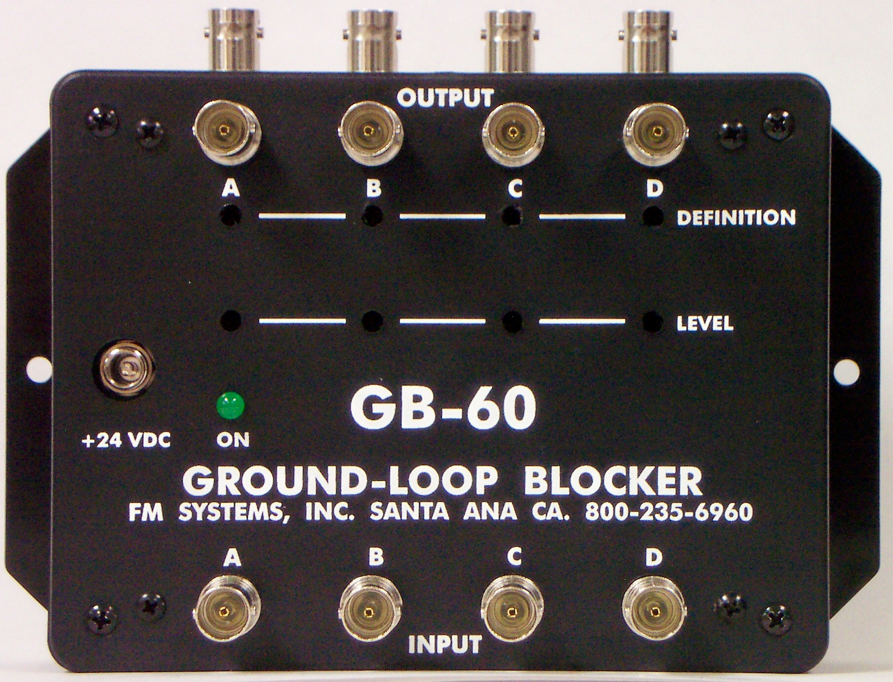
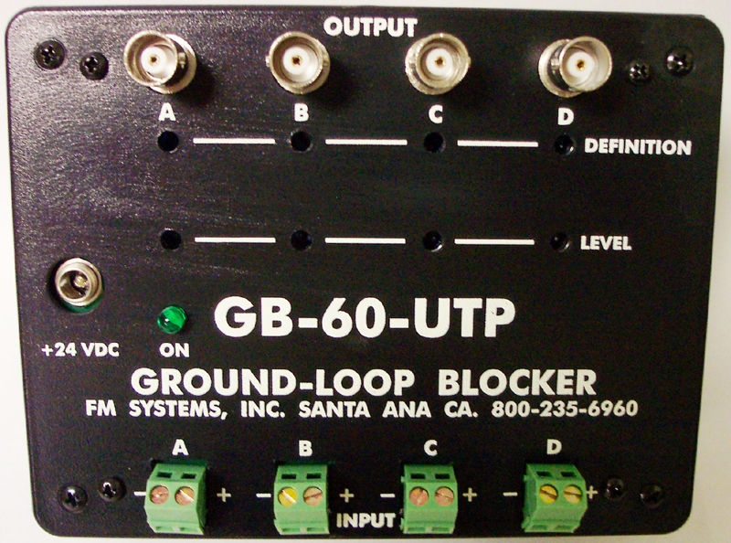
Cable slope loss can be minimized by using the best cable you can afford and be aware of termination errors that can cause unnecessary losses. If you have a long run and you need a cable equalizer contact FM SYSTEMS, INC at: 800-235-6960 and ask for the GB60 cable equalizer for Coaxial Cable and GB-60UTP for Twisted Pair Cable.