

PERFORMANCE TESTING FOR CABLE FIBER AND TWISTED PAIR INSTALLATION
PERFORMANCE TESTING FOR CABLE FIBER AND TWISTED PAIR INSTALLATION
By: Frank McClatchie
FM SYSTEMS, INC.
This guide will lead you through the test procedure for verifying operation of installed CCTV cable, twisted pair and fiber video transmission lines. Coaxial Cable and Twisted Pair video use the same procedure to measure the transmission capability of the video line. The fiber lines are tested in the same way except that they may have adjustments to compensate for video levels, we will also discuss the adjustment of those controls.
We will be testing the video lines for low frequency response and high frequency response. The low frequency response affects the uniform brightness of the picture and the ability of the monitor to synchronize with the camera. The high frequency response affects picture detail sharpness and color purity.
To test the response of your installed video cable, twisted pair or fiber you will need a video source. You may obtain a portable battery operated video generator or a color video camera can be used for this purpose. The generator will be a more accurate source, but the color camera will work for cable testing. If you use a color camera be sure to check it for proper operation before using it for a signal source. You can test the camera with the CM-1 CAMERA MASTER using the same testing procedure detailed later in this section. When using the color camera the lens will be covered by the lens cap and not removed during testing. The portable generator or color camera is temporarily connected to the video line to test for frequency response, and then moved to the next line for test and so on.
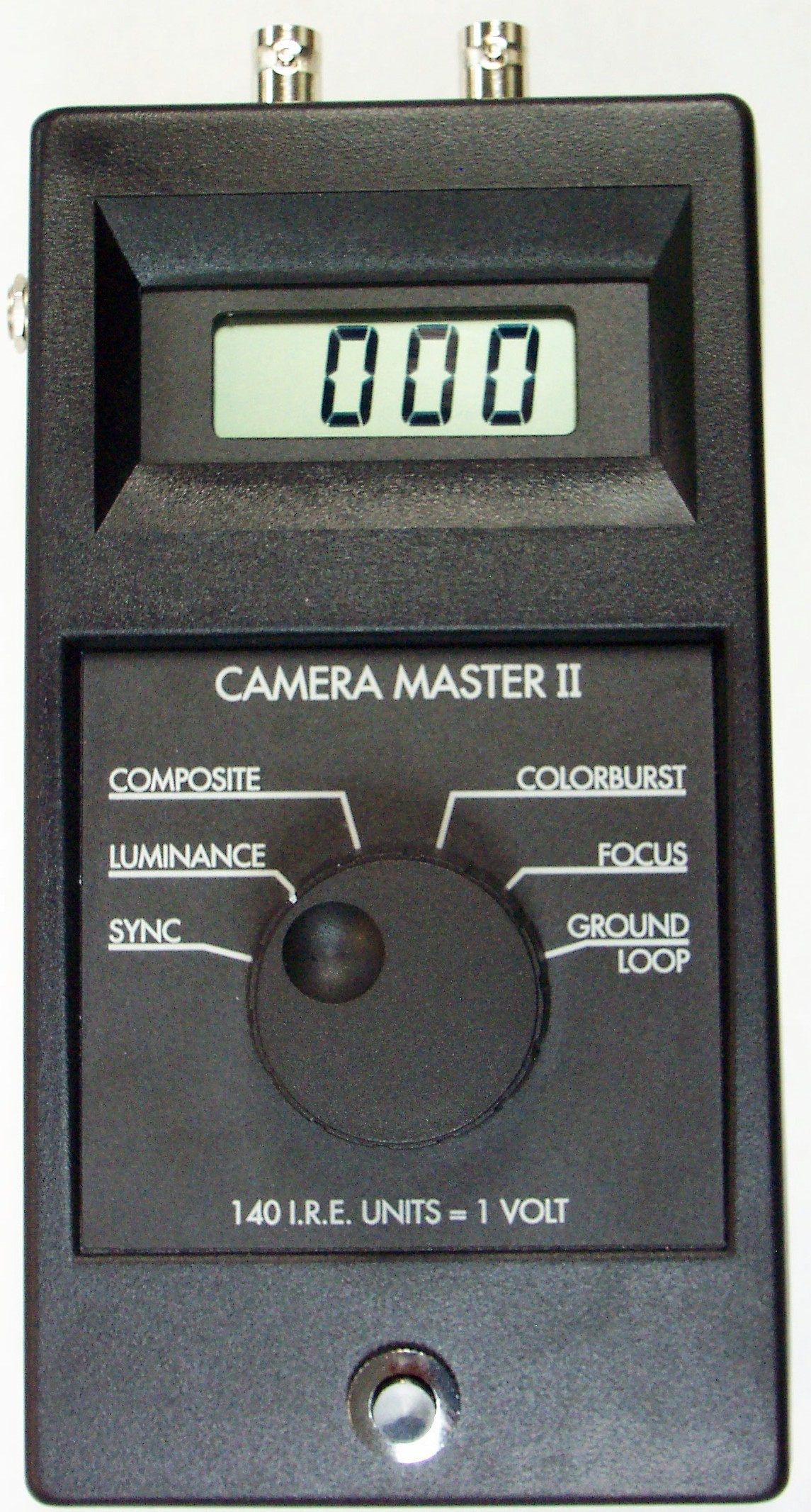
Use a CM-2 CAMERA MASTER test instrument to measure the frequency response. First connect the video generator to the beginning of the video line, where the camera will be connected.
Next go to the end of the video line and connect the CM-2 CAMERA MASTER to the open end of the video line. Be sure to terminate the video by placing a 75 Ohm BNC termination on the CM-2. When testing twisted pair installations attach the video generator to the BNC video connector on the twisted pair sender and the CM-2 to the BNC connector at the output of the twisted pair receiver. All measurements will be made with a 75 Ohm termination on the CM-2. You are now ready to make measurements of the video line.
Move the selector switch on the CM-2 to the SYNC position. The display should read 40 I.R.E. units +/- 5 I.R.E. units on short video lines, for longer video line refer to the CABLE SLOPE LOSS IN I.R.E UNITS table. This is the low frequency test for the video line. Next move the selector switch to the COLOR BURST position. The display should read 40 I.R.E. units +/- 5 I.R.E. units on short video lines, for longer video line refer to the CABLE SLOPE LOSS IN I.R.E UNITS table. This is the high frequency test. Cable length affects the high frequency more than the low frequency. Use the table supplied to check the video line for appropriate loss. The SYNC and COLOR BURST should be +/- 5 I.R.E. units measured against the table of cable length.
The next section is for the video equipment installer for measuring and setting the CCTV equipment so that the video levels are correct.
CCTV VIDEO TROUBLESHOOTING TIPS
Someone once said “Knowledge is the key to success”. This rule also applies to the installation and maintenance of CCTV camera equipment. Have you ever installed a CCTV camera system and then had to go back to solve a problem that was overlooked. A basic understanding of CCTV video signals, can save you hundreds of man hours, improve customer relations and increase job profitability all at the same time. This manual will discuss problems and solutions for CCTV camera installations.
To discuss video let’s start with the unit of measure, the I.R.E. unit. I.R.E. stands for Institute of Radio Engineers, this regulating body set the standards of measure for the video industry. This standard has been adopted by all industries in the United States and other parts of the world. 140 I.R.E. units are equal to 1 Volt Peak to Peak. I.R.E. units are easier to use because they divide into a video signal evenly.
For example proper Sync level on a camera is 40 I.R.E. units, the Voltage equivalent would be 0.2857143 Volts. Unfortunately this voltage cannot be measured on the Volt Ohm Milliamp Meter that you use for checking contacts. An oscilloscope has been used by some for this purpose, but it is bulky and does not read in I.R.E. Most people would rather use the simple 40 I.R.E. units of measure.
Fortunately hand-held battery operated meters to measure the video signal in I.R.E. units is available. This equipment is compact, extremely accurate and simple to use. Units like the “CAMERA MASTER” can even help to set the focus of a camera more accurately.
SYNC PULSE AMPLITUDE, HOW IT EFFECTS CCTV INSTALLATIONS.
A CCTV video camera creates synchronization pulses to lock the viewing monitor on the picture. These pulses occur at a rate of 15,750 times a second. There is one synchronization pulse or (sync pulse) for each line in the picture frame. The sync pulse tells the video monitor to start drawing a video line across the picture screen. When it gets to the end of the screen another sync pulse begins the next line and so forth until the screen has been filled with lines. It takes 262 and a half lines to form a frame, and two frames to form the video picture we see on the monitor.
The proper level for sync is 40 I.R.E. units. If the sync signal from the camera is too small in amplitude the picture will break up or roll. If the sync pulse is too big, any black portion of the picture will be more gray and the dynamic range of the picture will be degraded. Peak white level will also be compressed causing a blooming effect (loss of picture definition).
WHITE LEVEL IRIS SETTING, HOW MUCH IS ENOUGH?
There is a standard for Iris setting, or white level and it is 100 I.R.E. units. When setting a manual iris, or an automatic iris the level should be the same, 100 I.R.E. units.
If you set the iris below 100 I.R.E. units, the picture will be dim with less than desired dynamic range and the white picture elements will not be pure white. If you set the iris for more than 100 I.R.E. units, the picture can be washed out causing loss of picture definition.
Some cameras can be set to 120 I.R.E. units, but it should be noted that the standard is 100 I.R.E. units and in any case all cameras in the system should be set to the same level of white. This will ensure that the white portion of the picture will be the same brightness when a monitor is switched between them.
PEAK TO PEAK MEASUREMENT OF THE CCTV SIGNALS.
A quick measurement of the peak to peak video signal will re-assure you that the CCTV camera is putting out the right level. The standard level is 140 I.R.E. units.
COLOR CAMERA’S AND WHAT IS COLOR BURST ANYWAY?
More color cameras are being used in CCTV installations. The color camera adds a chrominance component (color information) to the signal, also known as Chroma. This Chroma signal operates at 3.58 Mega-Hertz. The standard level for the Chroma is 40 I.R.E. units. When the chroma level is low, the colors will be dull. If this level is too low, the color monitor will turn its color receiver off causing a Black and White only picture. This condition also indicates a loss of picture detail. You can see this effect on long cable runs.
The solution is to install a video equalizer in the line and adjust the color burst back to 40 I.R.E. units. If the Chroma signal is too high the picture will display color flaring and reduction of detail at the edge of the color flare.
VERTICAL INTERVAL, ITS MANY USES
The Vertical Interval (V.I.) is the part of the video signal that tells the monitor to start drawing a new screen. It is made up of special SYNC pulses with no picture elements. The standard level for these SYNC pulses is 40 I.R.E. units. All video SYNC pulses should be 40 I.R.E. units. The Vertical Interval is a very useful place to put alarm and control signals. Some manufacturers make equipment for pan and tilt camera control, alarm contact information, and data transmission that is inserted into the V.I. signal and sent up or down the cable.
TERMINATION, THE END OF THE LINE.
A termination for video is a 75 Ohm resistor placed at the end of any video cable to prevent signal reflections that cause ghosting or multiple images on the monitor. Some CCTV equipment have built-in terminations some of which are switch able. If you are using this equipment in series, you must switch off all terminations except the termination at the last piece of equipment in the cable run. Proper termination can be checked by measuring the SYNC pulse amplitude anywhere in the video cable. It should read 40 I.R.E. with the termination ON, and 80 I.R.E. with the termination OFF. If the SYNC level does not change when you remove the termination, the camera or video source is not standard 75 Ohms and should be serviced or replaced. Problems with V.I. control systems can result if the level does not double when you remove the termination.
THE BASIC THREE
To check performance of any CCTV camera installation make sure the SYNC level is 40 I.R.E. units +/- 5 I.R.E… WHITE level should be 100 I.R.E. units +/- 5 I.R.E… Remember if you want to run high white level say 120 I.R.E., be sure that all camera’s in the system have the same level of I.R.E +/- 5 I.R.E. Color burst level should be 40 I.R.E. units +/- 5 I.R.E.. SYNC, WHITE, and COLOR BURST are the three basic measurements to make to insure proper operation of your CCTV system. *
CCTV LINE-LOCK PROBLEM SOLVING TIPS
Someone once said “Timing is everything”. The same thing can be said about Line-Lock CCTV camera installations. The Line-Lock feature is available on most CCTV cameras, and is used to prevent picture rolling on the monitor during switching from one camera to another. Picture Roll will cause the loss of vital picture information in the video recorder and is irritating to view.
The CCTV camera puts out a series of pulses called “Sync” pulses that allow a video monitor to synchronize the picture on the screen. Special sync pulses called “Vertical Interval Pulses” tell the monitor to begin a new picture. The Vertical Interval Pulses from multiple cameras must be synchronized if you wish to switch from one camera to another without the monitor producing a picture roll. When a roll in the monitor occurs, the Vertical Interval can be seen as a black horizontal bar that appears Momentarily on the screen.
Let’s look at how the Line-Lock system keeps CCTV camera’s in synchronism. To synchronize multiple camera’s you must first have a common reference that is all the cameras must share the same timing information. The term Line-Lock refers to the 60 cycle AC (alternating current) supplied by the power company. This 60 cycle line frequency is the common reference used to lock the cameras together. For this reason only AC powered camera’s have the Line-Lock feature. DC powered camera’s are not capable of being Line-Locked.
When you select the Line-Lock feature in a camera there is internal circuitry that samples the 60 cycle AC frequency and uses it to time the Vertical Interval Pulses. All Line-Lock cameras’ have a Phase control that must be adjusted when the camera is installed. The Phase control is adjusted so that all the camera’s Vertical Intervals occur at the same time.
One way to adjust this Phase control is to switch between cameras and adjust the control until you no longer see the roll. This trial and error method is time consuming, requires 2 installers (one at the camera and one at the monitor) and is frustrating to accomplish. The preferred method is to use a VTM (Video Timing Meter) to adjust the Phase control.
An oscilloscope is an instrument that displays the waveform of the Vertical Interval Pulse. It is hard to set up, requires interpretation of the waveform, and is bulky in size.
The VTM timing meter is specifically designed to quickly adjust the timing error to zero with a digital readout that does not require interpretation of the waveform.
To make the Phase adjustment, you must select one camera as the reference. At the monitor point connect the output of the reference camera directly into the output of the camera that you wish to adjust, use a BNC Barrel connector. This makes the reference signal available at the camera to be adjusted.
Next go to the camera you wish to adjust and insert the VTM or oscilloscope between the camera and the cable you previously connected to the reference camera. Now adjust the camera Phase control to zero on the meter display or zero coincidence of the Vertical Interval Pulses on the oscilloscope. Repeat this step for each camera in the system using the same reference camera. When all cameras in the system are adjusted, no roll of picture will occur when you switch from one camera to another. Once the Phase controls have been carefully set in the system no further timing adjustments will be needed.
There is one exception. This carefully set Phase adjustment can be upset if the power circuits are re-balanced by an electrician at the power breaker box. When an electrician installs new power circuits into a commercial building, sometimes they will move the circuit breakers to a different Phase in the breaker box. In commercial buildings the utility power is Three Phase that is three separate 60 cycle lines whose phase is 120 degrees apart. Moving the power line that your camera is on to a different phase will throw off the timing and require a re-adjustment of the phase control on the camera.
If monitor personnel complain about picture roll, a fast check of timing can be made. Go to the monitor station and connect one camera as a reference to the VTM or oscilloscope and then connect each camera one at a time to make the measurement. The timing should be zero +/- 3 Video Lines or Sync Pulses. A roll can be noticed if the difference between cameras is more than a few lines. As the line difference between cameras’s increase so does the noticeable roll. If you measure a camera and the readings seem to change, that indicates the camera is not Line-Locked. The solution is to select the Line-Lock feature on that camera or replace it with one that can Line-Lock.
A clear understanding of how the Line-Lock system works combined with a way of measuring the Phase of each camera will let you set them quickly and correctly with confidence.
CCTV VIDEO GROUND LOOP PROBLEM SOLVING
When Video Ground Loop problems or 60 cycle Bars occur, they are easy to see on a video monitor. They look like a horizontal band or bar across the video monitor, that slowly moves up the video screen. These bars can be barely noticeable, or can be so bad that the video monitor loses lock and breaks up the picture. If the video camera is Line-Locked to the 60 cycle main power, the bars may stand still in the picture, but they still obscure picture definition and create customer complaints.
The source of the 60 cycle bar originates from the power industries use of local grounds to balance their power grid. Everywhere 60 cycle power is used, a local ground is attached to the power grid to return all unbalanced current flow to ground. As an example, you will notice that every main power breaker box will have a ground wire or conduit going to a ground rod or similar device connected to an earth ground. Every correctly installed power outlet will have a connection to this ground.
Not all grounds are created equal. In fact the earth ground in one building is most likely to have a different voltage potential relative to any other building, even grounds inside the same building will have different voltages between them, based on the uneven current flow of the power load.
Here is how the 60 cycle bar gets into your video picture. If you connect a coaxial cable to a monitor or other equipment that plugs into the 60 cycle main power and the other end of the coaxial cable becomes grounded locally for any reason a Ground Loop is created. Any difference in the 60 cycle voltage between these two ground points will create a current flow in the shield of the coax that induces the 60 cycle AC voltage into your video signal. It is easy to measure these differential voltages, simply disconnect the video cables at the monitor point and using your voltmeter on AC volts, measure between any two shields of the incoming video cables, you will be amazed at the difference.
The solution is to never connect both ends of a video cable to local grounds. Any cable can be grounded at one end without inducing the ground loop current. When you run coax cable from one building to another, it is acceptable to install through connection points, but do not allow the shields to come into contact with one another or the local ground.
A coaxial connector laying in a cable tray or conduit box can accidentally contact ground, don’t let this happen. Use tape on the connector to prevent accidental grounding. Also try not to attach the camera to any structure that is likely to be grounded. Remember that the camera is already grounded at the opposite end of the coaxial cable by the monitor equipment.
At the monitor station you may have many pieces of equipment connected together, like a ( Quad, Tape Recorder, Monitor) all of which plug into the main 60 cycle power. This will not present a problem if you plug all of the equipment into the same power line at the monitor point. Making sure that all the equipment share the same ground point at the monitor station. Also try to keep the video cables between equipment, (the service loops) as short as possible.
If you already have an installation that has 60 cycle bars, there are some steps you can take to solve the problem. If coaxial cable shields are connected together anywhere in the system, separate them if possible. Similarly remove all but one ground connection on each coaxial cable if possible, the ground is usually at the monitor end of the coaxial cable because the monitor equipment plugs into the 60 cycle main power supply which is grounded.
Sometimes a ground loop problem can be reduced by reversing the AC plug on the power transformer used to power the camera, or reverse the 24 VAC power connection to the camera. This technique will not work on DC powered cameras.
If the problem still persists, video isolation transformers can be installed at one end of the coaxial cable to block the shield current flow and eliminate the 60 cycle bars. These transformers must be installed at the coaxial cable that is originating the 60 cycle bar problem. Isolation transformers only work when they can block the current flow in the shield. Once 60 cycle bars become part of the video signal, no economical down stream solution will remove the bars.
Use a portable monitor to find the origin of the ground loop problem, start at the camera and move down the coaxial cable until you see the bars appear on the portable monitor. This then is the coaxial cable with the current in the shield. Clear the ground connection or install an isolation transformer at this point. With an understanding of Ground Loop problems and the use of good single ended grounding techniques, you should be able to keep the 60 cycle bars out of your CCTV installations.
|
CABLE SLOPE LOSS IN I.R.E. UNITS
|
|||
|
CABLE LENGTH IN FEET
|
SYNC PULSE
|
LUMA WHITE
|
COLOR BURST
|
|
0
|
40
|
100
|
40
|
|
50
|
39
|
99
|
37
|
|
100
|
39
|
98
|
35
|
|
200
|
39
|
98
|
34
|
|
300
|
38
|
97
|
32
|
|
400
|
38
|
97
|
31
|
|
500
|
37
|
96
|
29
|
|
600
|
37
|
96
|
27
|
|
700
|
36
|
95
|
25
|
|
800
|
35
|
93
|
23
|
|
900
|
35
|
92
|
22
|
|
1000
|
34
|
92
|
20
|
|
1100
|
34
|
91
|
19
|
|
1200
|
34
|
91
|
18
|
|
1300
|
33
|
90
|
17
|
|
1400
|
33
|
90
|
16
|
|
1500
|
32
|
89
|
15
|
|
1600
|
32
|
89
|
14
|
|
1700
|
32
|
89
|
13
|
|
1800
|
31
|
88
|
12
|
|
1900
|
31
|
87
|
11
|
|
2000
|
30
|
87
|
10
|
CALL 800-235-6960 or CLICK HERE AND START TESTING TODAY!