BEST PRACTICE FOR MEASURING P.O.E.
By: Don McClatchie
The use of P.O.E. Power Over Ethernet is increasing do in part to the development of the standard IEEE802.3af with more manufacturers incorporating P.O.E. capability into their products. The advantages of using P.O.E. as a source of power are numerous including. No need for an electrician and no dangerous high voltage main wiring, the equipment can be moved from place to place without having to install new power sources, equipment can be shut down or re-set remotely, power can come from a common source without additional wiring and using one single crimp 8P8C connector to attach the equipment for both data and power is easer.
Every P.O.E. power system has at least two parts, the power sourcing end often referred to as the “PSE” or Power Sourcing Equipment and the load end of the system called the “PD” or Powered Device. The PSE can be built into the NVR, a network switch, or into a P.O.E. injector. In all cases the power to run the equipment originates in the PSE device. It is built to avoid overloads and short circuits by protecting the source supply in several ways. The first way begins at start up when the PSE is powered up it will test the network cable with a current limited low voltage looking for a particular resistance load of “25K Ohms” to see if any PD equipment is connected to it. If no equipment is connected to the PSE it will not provide power to the line but instead will continue to test the line for a valid load. If the load is too heavy for the supply then the PSE will not connect the power. So for a PSE to supply the necessary voltage there must be a suitable load and it cannot exceed the maximum power supply capability. In this way the PSE protects the network cable from being overpowered and also protects the PSE equipment from being overloaded. The P.O.E. system operates between these two extremes and it is the operational voltages that should be measured when installing a new P.O.E. system or when you troubleshoot an existing system.
Now at the other end of the network cable is the PD or Powered Device, typically the camera. Inside the PD is another DC to DC converter to take the highly variable voltage (caused by cable DC Loss) from the network cable and regulate it for a stable camera voltage. This all works out pretty good provided the PSE delivers enough voltage to keep the PD regulators supplied. When and if they don’t your camera is likely to go off line or the data will become intermittent.
So what should the technician be looking for in a good P.O.E. supply voltage? The supply voltage as measured on the PSE side of the network cable should be from 36 to 57 VDC with a voltmeter on DC, 200 Volt range with the system under full load. However you should see a nominal voltage of 48 VDC.
As a result of DC resistive cable loss the voltage on the PSE side of the cable will always measure larger than the voltage on the PD side of the network cable. So that makes the measurement taken at the PD end of the network cable the most critical measurement. On the PD side your delivered voltage must be high enough to supply the DC to DC electronics inside your camera. If this voltage level dips down during operation the camera data could be affected. You should measure and record the DC voltage delivered to the PD with a standard voltmeter when installing a new P.O.E. system and when troubleshooting an existing system.
There is a measurement of the P.O.E. supply that is often overlooked, and that is measurement of AC ripple on the supply and sometimes an interfering AC signal that can affect your cameras operation and can even cause errors in the data transmission. This AC signal will ride on top of the DC voltage like noise and if it is severe enough it can enter the data through the components in the camera. Most of the time you should not be able to detect the AC signal, however if it is large enough it will be a problem. So you should switch your Voltmeter over to the AC side with a range of 50 VAC and measure for any interfering AC voltage. So now you know what to measure, what’s next?
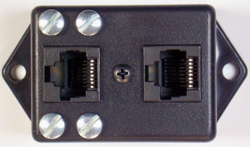
The next task is to find a simple and clean way to break into the network cable to make the measurements without damaging the cable in the process. The best way is to make up a special connector box with two female 8P8C connectors on it so that you can insert it anywhere there is a connector along the network cable path to measure the P.O.E. voltages. This adapter box should give you easy access test points for the P.O.E. voltage on pins 1/2-3/6 and 4/5-7/8 both methods used in the P.O.E. system. Then you just touch the voltmeter to the test points and take the DC and AC measurements, it’s just that easy.
FM SYSTEMS, INC. makes just such a device to measure the P.O.E. voltage called the POET-1. It is designed to give you access to the P.O.E. voltage in your IP system for easy measurements. It is a rugged, low cost tool you will use to verify the P.O.E. voltage in your installations.