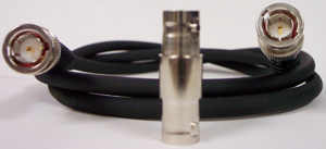
ATTENUATION OF STANDARD COAXIAL CABLE
ATTENUATION OF STANDARD COAXIAL CABLE
By: Don McClatchie
Coaxial cable is used widely in most types of communication systems. The properties of the coaxial cable make for a good wide-band path for all kinds of electronic signals. In fact, over 80 percent of the homes in the USA have one or more coaxial cables connected to them. Industries like Radio Broadcasting, Television Broadcasting, Cable Television, Telephone Companies, Microwave Transmission, and Data communications over the internet all rely on this type of cable. Most Coaxial cable is made up of copper wire and insulation material with some types of cable using copper plated steel as the conductors, so the signal loss can vary widely. The main factor in cable loss comes from the type of insulator material used and the mechanical size and manufacturing methods so the loss can vary slightly from one manufacture to another. This table shows the losses of signal through the cable at different frequencies in dB “decibels”. This frequency selective attenuation of signal level is also referred to as Cable Slope Loss. The Capacity of the cable and the inductance along its length causes a greater roll off at higher frequencies.
| dB ATTENUATION OF STANDARD COAXIAL CABLE | ||||||||||||||||||
| CABLE TYPE | RG-174 | RG-58 | RG-58/U | RG-58X | RG-59 | RG-213 | RG-214 | RG-6 | RG-11 | RF9913 | RF-9914 | LMR-195 | LMR-200 | LMR-240 | LMR-400 | LMR-600 | LMR-900 | LMR1200 |
| dB LOSS PER 100 FEET | ||||||||||||||||||
| FREQUENCY | ||||||||||||||||||
| 1 MHz | 1.9 | 0.4 | 0.5 | 0.2 | 0.2 | 0.2 | 0.2 | 0.3 | ||||||||||
| 10 MHz | 3.3 | 1.4 | 1.0 | 0.6 | 0.6 | 0.4 | 0.4 | 0.5 | ||||||||||
| 30 MHz | 2.5 | 2.0 | 1.2 | 1.2 | 0.8 | 0.8 | 1.8 | 1.8 | 1.3 | 0.7 | 0.421 | 0.288 | 0.209 | |||||
| 50 MHz | 6.6 | 3.3 | 3.1 | 2.5 | 2.4 | 1.6 | 1.6 | 1.4 | 1.0 | 1.1 | 1.1 | 2.3 | 2.3 | 1.7 | 0.9 | 0.547 | 0.374 | 0.272 |
| 100 MHz | 8.9 | 4.9 | 3.6 | 3.4 | 2.2 | 2.0 | 1.6 | 1.4 | 1.5 | |||||||||
| 144 MHz | 6.2 | 4.6 | 2.7 | 2.7 | 1.6 | 3.0 | 1.4 | 0.960 | ||||||||||
| 150 MHz | 6.2 | 4.7 | 2.8 | 2.8 | 1.7 | 1.7 | 4.0 | 3.9 | 3.1 | 1.5 | 0.964 | 0.658 | 0.481 | |||||
| 200 MHz | 11.9 | 7.3 | 5.4 | 3.3 | 2.8 | 2.3 | 1.8 | 2.0 | 3.6 | |||||||||
| 220 MHz | 7.4 | 7.4 | 6.0 | 3.5 | 3.5 | 2.1 | 2.1 | 4.8 | 4.8 | 3.7 | 1.8 | 1.180 | 0.803 | 0.589 | ||||
| 400 MHz | 17.3 | 10.1 | 7.9 | 7.0 | 4.8 | 4.3 | 3.5 | 2.6 | 2.9 | |||||||||
| 450 MHz | 10.6 | 10.6 | 8.6 | 5.2 | 5.2 | 3.1 | 3.1 | 7.0 | 6.9 | 5.3 | 2.7 | 1.720 | 1.170 | 0.864 | ||||
| 700 MHz | 26.0 | 16.9 | 11.0 | 6.6 | 5.6 | 4.7 | 3.6 | 3.8 | ||||||||||
| 900 MHz | 27.9 | 20.1 | 16.5 | 12.6 | 11.1 | 7.9 | 7.9 | 6.0 | 5.4 | 4.1 | 4.5 | 9.9 | 9.9 | 7.5 | 3.9 | 2.500 | 1.700 | 1.270 |
| 915 MHz | 20.2 | 12.8 | 8.0 | 8.0 | 4.2 | 7.6 | 4.0 | 2.510 | ||||||||||
| 1 GHz | 32.0 | 21.1 | 13.5 | 12.0 | 8.3 | 6.2 | 5.6 | 4.5 | 5.3 | |||||||||
| 1.2 GHz | 21.5 | 15.9 | 10.1 | 10.1 | 5.2 | 9.2 | 4.8 | 3.100 | ||||||||||
| 1.5 GHz | 6.0 | 12.9 | 12.7 | 9.9 | 5.1 | 3.310 | 2.240 | 1.690 | ||||||||||
| 2.4 GHz | 32.2 | 23.1 | 15.2 | 15.2 | 7.7 | 12.9 | 6.8 | 4.400 | ||||||||||
| 5.8 GHz | 51.6 | 40.9 | 28.6 | 28.6 | 13.8 | 20.4 | 10.8 | 7.300 | ||||||||||
| IMPEDENCE | 50 Ohm | 50 Ohm | 50 Ohm | 50 Ohm | 75 Ohm | 50 Ohm | 50 Ohm | 75 Ohm | 75 Ohm | 50 Ohm | 50 Ohm | 50 Ohm | 50 Ohm | 50 Ohm | 50 Ohm | 50 Ohm | 50 Ohm | 50 Ohm |
| CABLE TYPE | RG-174 | RG-58 | RG-58/U | RG-58X | RG-59 | RG-213 | RG-214 | RG-6 | RG-11 | RF9913 | RF-9914 | LMR-195 | LMR-200 | LMR-240 | LMR-400 | LMR-600 | LMR-900 | LMR1200 |
All the numbers in this table represent Loss and so by definition are all negative numbers.
If you work with RF signals like SDI data and want to measure signal levels on coaxial cable you can CLICK HERE to see our SDI-2 meter.


