Serial and Parallel data communication has been with us since the dawn of computers and connecting other devices to those computers have always required various types of hardware and wiring. This article gives examples of the most common connection methods old and new, and the wiring scheme for the connection. This list shows the type of connector and the pin wiring for that connector. The IEEE-488 GPIB I/O interface is also listed for those people interested in remote control of instrumentation and testing equipment.
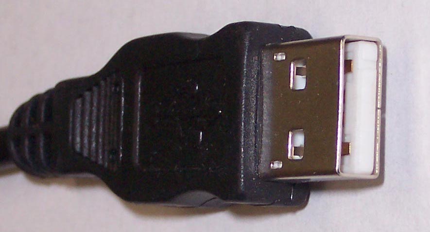
USB UNIVERSAL SERIAL BUSS
Pin #
Signal
Function
Signal
Description
Direction
On Device
1
RED WIRE
+ 5 Volt (VSS)
None
2
WHITE
DATA –
In/Out
3
GREEN
DATA +
In/Out
4
BLACK
Ground
None
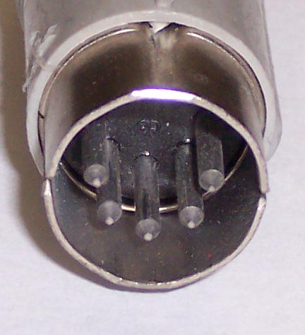
PS2 Keyboard 5 Pin DIN SERIAL BUSS
Pin #
Signal
Function
Signal
Description
Direction
On Device
1
CLOCK
Clock Data In and Out
Output
2
DATA
Data Line
In/Out
3
NONE
Not Connected
None
4
GROUND
Ground for +5, Data & Clock
None
5
+5 VOLTS (vcc)
Power Supply VCC
None
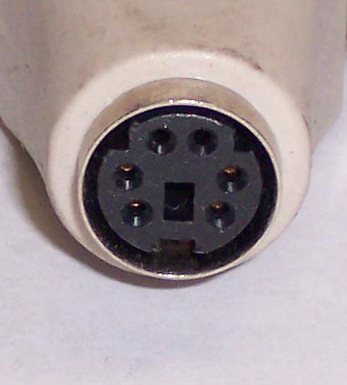
PS2 Keyboard 6 Pin Mini DIN
Pin #
Signal
Function
Signal
Description
Direction
On Device
1
DATA
Data Line
In/Out
2
NONE
Not Connected
None
3
GND
Ground for +5, Data & Clock
None
4
+5 VOLTS (vcc)
Power Supply VCC
None
5
CLOCK
CLOCK
Output
6
NONE
Not Connected
None
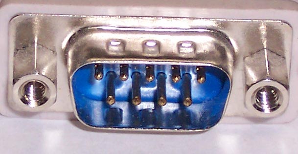
RS232C Serial Interfaces I/O Standard DB9 Pin Connector (IBM)
Pin #
Signal
Function
Signal
Description
Direction
On Device
1
DCD
Data Carrier Detect
Input
2
RD
Receive Data
Input
3
SD
Transmit Data
Output
4
DTR
Data Terminal Ready
Output
5
SG
Signal Ground
None
6
DSR
Data Set Ready
Input
7
RTS
Request to Send
Output
8
CTS
Clear to Send
Input
9
RI
Ring Indicator
Input
RS232C Serial Interfaces I/O Standard DB9 Pin Connector (Macintosh)
Pin #
Signal
Function
Signal
Description
Direction
On Device
1
GND
Ground
None
2
No Connection
None
3
SG
Signal Ground
None
4
No Connection
None
5
TD
Transmit Data
Output
6
DTR
Data Terminal Ready
Output
7
DSR
Data Set Ready
Input
8
No Connection
None
9
RD
Receive Data
Input
RS232C Serial Interfaces I/O (Apple IIc) Round Pin Connector
Pin #
Signal
Function
Signal
Description
Direction
On Device
1
DTR
Data Terminal Ready
Output
2
TD
Transmit Data
Output
3
GND
Ground
None
4
RD
Receive Data
Input
5
DSR
Data Set Ready
Input
RS232C Serial Interfaces I/O (Commodore 64) Round Pin Connector
Pin #
Signal
Function
Signal
Description
Direction
On Device
1
SRQIN
Serial SRQIN
Input
2
GND
Signal Ground
None
3
SA
Serial Attn I/O
In/Out
4
SC
Serial Clock I/O
In/Out
5
SD
Serial Data I/O
In/Out
6
RS
Reset
Input
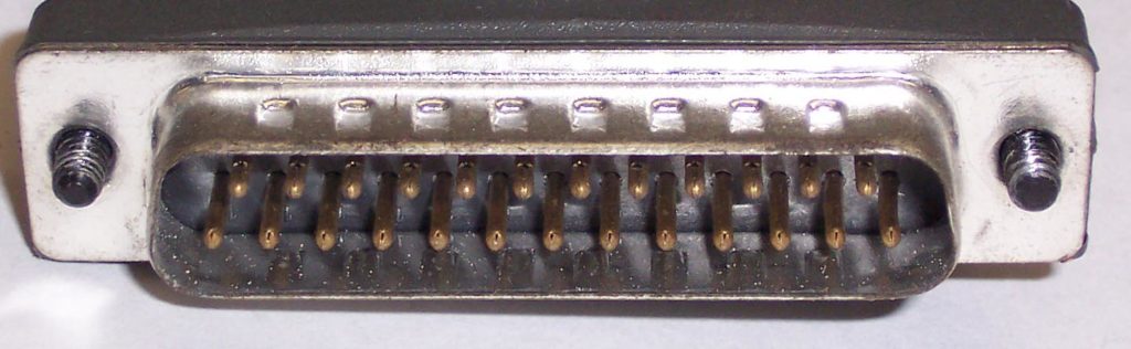
IBM / MSDOS DB25 Parallel Connector Computer Side
Pin #
Signal
Function
Signal
Description
Direction
On Device
1
STROBE
Clocks In Data
Output
2
DATA BIT 0
Data Line
Output
3
DATA BIT 1
Data Line
Output
4
DATA BIT 2
Data Line
Output
5
DATA BIT 3
Data Line
Output
6
DATA BIT 4
Data Line
Output
7
DATA BIT 5
Data Line
Output
8
DATA BIT 6
Data Line
Output
9
DATA BIT 7
Data Line
Output
10
ACKNLG
Acknowledge Receipt
Input
11
BUSY
Printer is Busy
Input
12
PAPER EMPTY
Printer Out of Paper
Input
13
SLCT
Online Mode Indicator
Input
14
AUTO FEED XT
Output
15
FAULT ERROR
Indicates Offline Mode
Input
16
INIT
Resets Printer Clears Buffer
Output
17
SLCT IN
TTL High Level
Output
18
GROUND
Ground Return for Pin 1-12
Output
19
GROUND
Ground Return for Pin 1-12
Output
20
GROUND
Ground Return for Pin 1-12
Output
21
GROUND
Ground Return for Pin 1-12
Output
22
GROUND
Ground Return for Pin 1-12
Output
23
GROUND
Ground Return for Pin 1-12
Output
24
GROUND
Ground Return for Pin 1-12
Output
25
GROUND
Ground Return for Pin 1-12
Output
IEEE-488 GPIB I/O Interface 24 Line Parallel Buss Connector