

HOW TO CREATE SUPERIOR QUALITY CCTV PICTURES ON UTP & HOW TO PROVE RESULTS WITH THE 40-40 QUALITY TEST
HOW TO CREATE SUPERIOR QUALITY CCTV PICTURES ON UTP
AND
HOW TO PROVE RESULTS WITH THE 40-40 QUALITY TEST
Author: Frank McClatchie, president, FM Systems, Inc.
Phone: 800-235-6960 Fax: 714-979-0913
Very high quality video pictures can be sent over Unshielded Twisted Pair (UTP) wires, provided that suitable cable slope equalizers and amplifiers are provided to completely off-set the losses incurred when the video signal traverses the UTP cable pairs. When this is done, the picture received at the far end of the cable will be every bit as good as the Camera , Recorder, and Monitor are able to produce, with no degredation due to losses in the intervening transmission facilities, whether UTP, Coaxial Cable, or Impedance Converters such as Senders and Receivers. In fact, once the cable losses have been correctly equalized, further picture quality improvement can only be acheived by using superior quality Cameras, Recorders, and Monitors.
Many CCTV installers have found that high quality Cameras, Recorders, and Monitors do not seem to provide better overall picture quality than lower quality terminal equipment when used on long UTP transmission facilities. The reason is simple. All of the crisp high quality detail created by the high quality terminal equipment (cameras, etc.) has been lost trying to get through the losses created by the Senders, UTP wires, and Receivers. The only way to upgrade picture quality is to correct the transmission facility losses by using cable equalizers and amplifiers to off-set these losses. It is also very important to realize that, in the case of twisted wire equalization, “more is not better”. Only the correct amount of equalization will do. More of the same will only make the video picture worse, instead of better.
So to get the best possible picture with any given terminal equipment / transmission facility, careful measurement of cable losses at both low and high frequencies need to be made with suitable test generators and measurement equipment. Then adjustable cable equalizers and can be installed to off-set transmission losses.
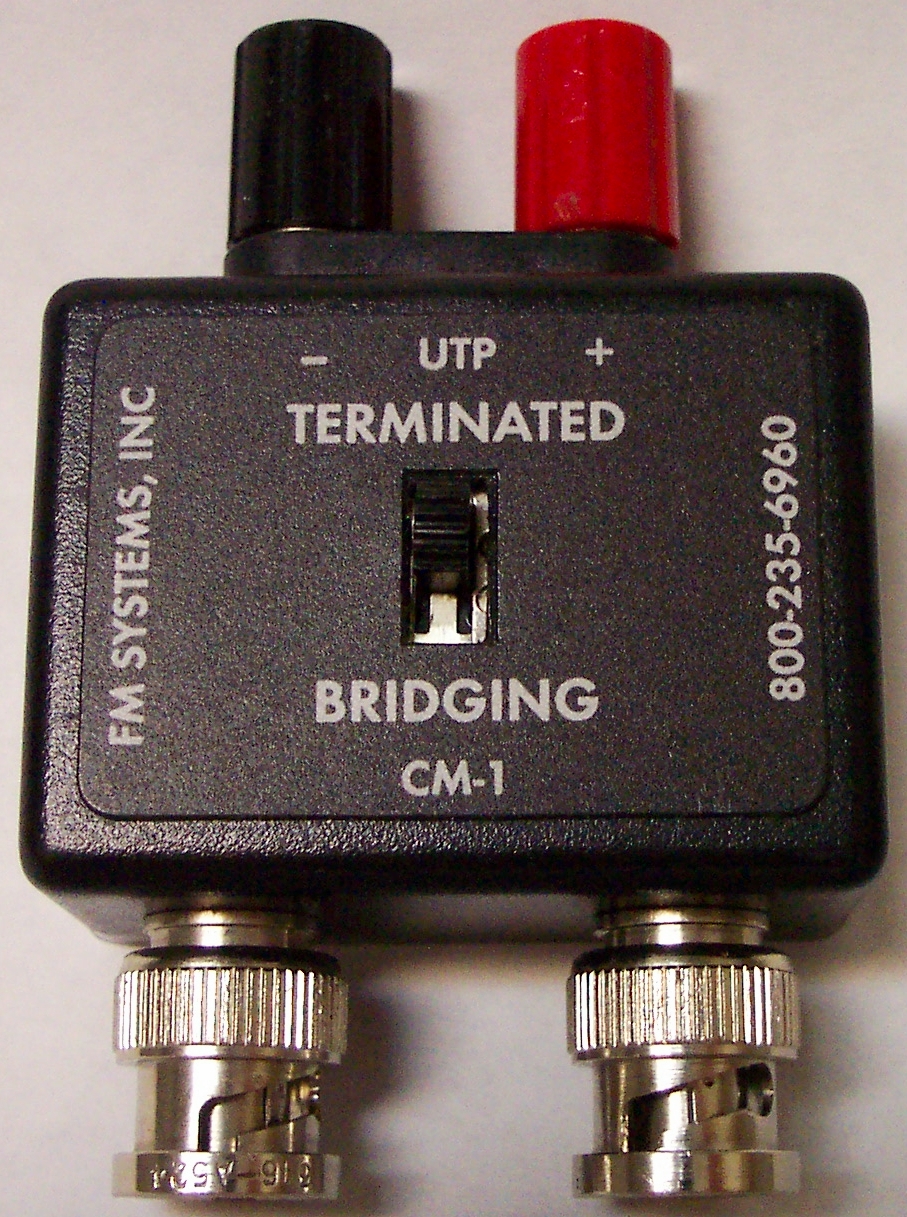
When dealing with UTP transmission facilities, the test equipment will have to operate at both 75 Ohm unbalanced impedance and also 105 Ohm balanced impedance. Both of these kinds of measurements can be made using the CM-2 Camera Master (a 75 Ohm video signal tester) together with the CM-1-UTP (a balanced 105 Ohm adapter). The CM-2 measures the video signal in I.R.E. Units of measurement. The I.R.E. Unit is the International standard for video meaurements, not Volts peak-to-peak. The reason is, that I.R.E. Units are much easier to read and calculate with (i.e., a correct SYNC. pulse amplitude in IRE Units is 40, while in Volts peak-to-peak the measurement is 0.285714 Volts).
The VLTG-800 Video Line Test Generator is used to generate the full range of signals needed to test a transmission facility for quality. If the VLTG-800 is not available, these quality tests can be performed using a Color Camera as a signal generator (with somewhat less accuracy). The 15,750 Hz Sync. pulse of the VLTG-800 or Color Camera provides the test signal for low frequency “luminance” amplitude test, while the 3.579 MHz Color Burst, also transmitted by the VLTG-800 or Color Camera generates the high frequency “Chromanance” amplitude test signal.
The Sync. pulse from the test generator will have an amplitude of 40 I.R.E. Units and the Color Burst will also measure 40 I.R.E. Units at the test generator output. The longer the transmission facility, the smaller these measurements will be, with the Color Burst measurement reducing much faster than the Sync. signal. A perfect transmission would read 40 I.R.E. Units of sync. and 40 I.R.E. Units of Color Burst at the far end of the system (at the Monitor) and could be designated a 40-40 perfectly equalized system, whereas either a higher or lower reading would constitute a non-equalized less than optimum transmission of the video signal.
A perfect 40-40 test signal will be degraded to about 35-21 by the time that 500 feet of UTP wire has been traversed. this means that the luminance (brightness) of the picture will be 35/40, or 87.5% of normal level, and the picture detail will be 21/40, or about 52.5 % of what the camera generated ! Almost one-half of the picture detail is now gone. This results in the dull less than sharp picture image.
At about 1000 feet the test signal will be degraded to 31-11. The picture brightness will be down to 31/40 or 77.5% of normal (or a loss of 22.5% of the original signal. The picture detail will now be 11/40 or 27.5 % of the original picture detail, a loss of 72.5% !
In each case, the picture brightness can be compensated for by increasing the contrast control of the Monitor, but who wants to keep changing that control each time a new camera is switched on-line. No such adjustable control is readily available to off-set the loss of high frequency response. the picture detail is lost forever unless equalizers are provided to compensate for this loss.
As the UTP or coaxial cable gets longer, of course the picture gets dimmer and the detail gets fuzzier unless equalizers are provided in the CCTV design. The following chart shows the sort of loss that can be expected for various lengths of UTP wires. Losses incurred by passive Senders and Receiver can add significantly to the total losses that may be incurred.
|
24 GAUGE UN-EQUALIZED UTP CABLE LOSS
|
||||||
| Length |
Sync. (low frequency)
|
Color Burst (high frequency)
|
||||
|
IRE Units
|
% Loss
|
Notes
|
IRE Units
|
% Loss
|
Notes
|
|
| 0′ |
40
|
0%
|
40
|
0%
|
||
| 500′ |
35.2
|
11.9%
|
#1
|
21
|
52.6%
|
#6
|
| 1000′ |
31
|
22.4%
|
#2
|
11
|
72.4%
|
#7
|
| 1500′ |
27.4
|
31.6%
|
#3
|
5.8
|
85.5%
|
#8
|
| 2000′ |
24.1
|
39.7%
|
#4
|
3
|
92.4%
|
#9
|
| 3000′ |
18.7
|
53.2%
|
#5
|
0.8
|
97.9%
|
#10
|
NOTES:
| #1. Slight loss of brightness #2. Greater brightness loss #3. Serious loss of brightness #4. Possible Sync. loss #5. Probable Sync. loss |
#6. Week color, one-half the detail #7. Very weak color, poor detail #8. Color faded out, very poor detail #9. Color gone, low quality picture #10.No color, very poor detail |
It is clear from the chart above, that while picture brightness does degrade on longer UTP wires, the picture details and color brightness degrade at a much greater rate with wire pair length.
To attempt SUPERIOR QUALITY CCTV OVER UTP FACILITIES, it is clear that any UTP wire pair length greater than about one hundred feet or so will need to be equalized to compensate for cable pair loss as well as the losses in passive Senders which can exhibit up to 50% loss of high frequencies.
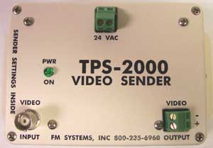
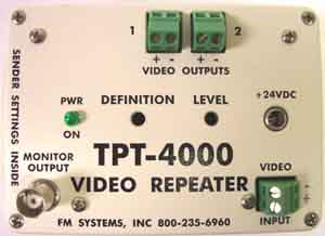
Summary
To produce superior quality CCTV , use the VLTG-800 generator and a CM-2 Camera Master equipped with a CM-1-UTP adapter to measure test results. To obtain 40-40 results, use the TPS-2000 pre-equalizing Sender, the TPT-4000 equalizing Repeater and Line Splitter, and the GB-60-UTP equalizing Receivers. Please contact FM SYSTEMS, INC. at 800-235-6960 or 714-979-3355 for additional information.

CM-2 Video Master Test Meter